R1155 PSU Addendum
2 minute read
March 2020
Oops! ...
Correction to schematic for 220V PSU and External Audio Amplifier
Back in January 2012 I wrote a piece on the PSU that powers my T1154M/AD8882B combination. Now in March 2020, as I am putting the final touches to a PSU/Audio Amp for someone else, I find myself questioning the schematic for the 220V supply and external audio amplifier.
The main issue stems from the way the HT (220V) from the dynamotor was connected to the R1155 via pins 8 & 5 on P1. This in conjunction with what we might call 'the Bias Board' ensures that the chassis 'floats'. Although we can still refer to the chassis as 'ground' where the RF and AF signal paths are concerned, the chassis actually sits at around +30V with respect to HT-. In other words a negative bias rail is created for controlling the gain of the RF and IF stages.
This must be taken into account when adding any additional audio stage which runs from the same HT supply as the receiver. If you don't want to make modifications to your R1155 it is possible to simply use the Phones output on P1 pin 6 and feed it into your amplifier of choice. In my case this is a Russian 6P1P, or you could use a 6V6. The Phones output on the R1155 is the secondary winding on L30 in the Anode circuit of V8. One end of this winding is connected to Ground (the chassis). See the schematic diagram below ...
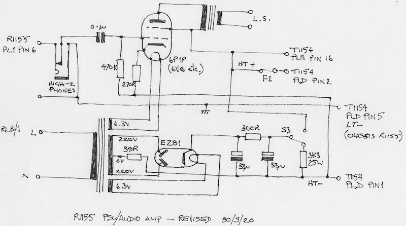
Revised (corrected) schematic for HT (220V) supply and external Audio Stage
Note that the returns for the Grid resistor (470K) and Cathode resistor 270R in the audio stage are NOT connected to the chassis but instead go direct to the HT- rail. If on the other hand these two resistors were connected to the chassis (signal ground), the combined Anode And Screen currents pertaining to the valve would flow through the network of resistors in the bias board and thus change the level of -ve bias.
Curious as to why my original schematic was incorrect, I went searching on-line for R1155 modifications ... and I found a couple of articles where although the Jones Connector pin numbers were correct (i.e. the Grid and Cathode resistors were connected to HT-), the line was also labelled 'GND' or had a Chassis symbol against it. So maybe that was where the confusion crept in? And just to be sure in my own case, I heaved my PSU off the shelf under the desk (NOT and easy task!) and removed the bottom cover. To my relief my own PSU was in fact wired correctly.
Note that the 3K3 load resistor is now correctly shown connected to HT-.