Automatic Preselector MA1101A
10 minute read
June 2024
Due to the nature of many of the 'well known' courier services here in the UK, it has taken no less than twelve months for these two items (see below) to get to me. Since too many of them now limit the maximum weight of a package to a maximum of 35Kg, my client was at pains to find a courier willing and able to handle two bespoke wooden crates. However, just over a week ago I took delivery of the two crates ... I now had to find the time to slot them into my seemingly never-ending queue of valve-based Racal kit in for refurbishment
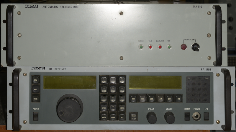
MA1101A and RA1792, in for repair
The MA1101 comes in three 'flavours': A, B and C. The MA1101A is best suited for use with a receiver where the first Local Oscillator is either 35.4MHz - 65.4MHz, or 40.455MHz to 70.455MHz. The MA1101B is specifically designed for use with the MA1720 Drive Unit, with frequency tracking facilitated by way of parallel input lines. The MA1101C could be considered an amalgam of the two with an internal link allowing the user to select whether the Preselector is to be used with either a receiver or a transmitter.
The problem with this particular MA1101A was that the blower at rear, which according to the manual, should to stop 16 seconds after tuning, did NOT stop. To me, that sounded simple enough. However, in order to work on the preselector, I would first have to repair the RA1792, and although I had a very good idea what was wrong with the receiver, it was likely to prove a lengthy diagnostic affair.
Essentially the two LCD displays were corrupted ... not physically as often happens when the bond between the layers breaks down. No, the problem here was very clearly a symptom of a damaged Processor board ... very likely the result of a leaking NiCad backup battery. I was correct.
It was an interesting example of the 1792 in that the first thing that struck me was the lack of an ovenised 5MHz crystal oscillator. This is the first RA1792 that I have encountered with the 5MHz oscillator mounted on the 2nd LO Synthesiser board. A quick look at the Processor board confirmed my suspicions ... the second-generation NiCad battery had indeed leaked a nasty corrosive residue over the surrounding board ... no doubt to the detriment of the tiny tracks and via-holes in the neighbourhood.
It took me a couple of days and involved the tedious task of verifying the integrity of every single PCB track on the board. In the end, I identified two open-circuit tracks (duly by-passed) and a faulty Octal D-Type Latch. On replacing the IC, the receiver burst into life. However the SCORE card which had been connected to the Processor board was clearly damaged and when I reconnected it the receiver stopped working. I had a spare SCORE card which I fitted. Although I have no way of testing it, it did not crash the Processor. The SCORE card in this configuration (RA1792 and MA1101A) is actually redundant. Another thing about this particular RA1792 is that every singe IC is socketed ... making IC replacement so much easier.
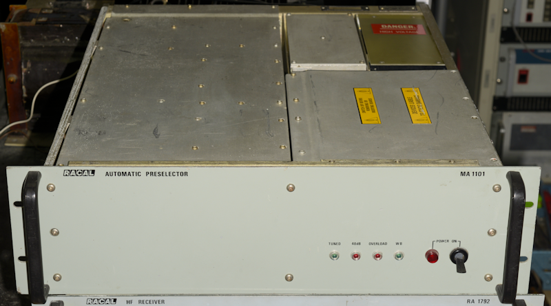
So with the receiver now working again, I moved on to the MA1101A. As previously said, the fault lay with the blower, which was NOT shutting off after 16 seconds. Such was the noise from the blower, the owner had taken to cutting the wires and physically removing the offending fan from the chassis. Because the MA1101A is designed to be fitted into a rack, it has no top and bottom covers. However, this one had an aluminium sheet gaffer-taped to the top ... very likely to stop things falling inside.
MA1101A - Top exposed
On the right we have the PSU and Protection module at the rear. Also on this side we have what Racal describe somewhat confusingly as the Motherboard. This is nothing more than a back-plane for the rack of eight vertically mounted double-sided PCBs, where like the accompanying RA1792, all the CMOS ICs are in sockets. Fortunately, the owner had provided a service manual. This looked like a photocopy that had originally been in a 2-ring binder, but had then been 'upgraded' to a 4-ring binder with each page in a 'polly-pocket' ... however it did look that it might be incomplete and I got the impression that some of the pages had been 'shuffled' ... hmmm? So I spent a few hours sorting the pages into what I perceived was the correct order.
Happy that none of the schematics or layout diagrams were missing, I set about identifying the circuitry responsible for switching the fan on and off. This proved to be a somewhat devolved circuit. The Interconnection Diagram shows the fan connected directly (via a connector) to the PSU. Incidentally, the fan runs from a 120V AC supply. I do hope it was NOT running when the wires were cut! The PSU schematic shows that the fan is switched OFF and ON by way of a 12V relay which is mounted on the PSU PCB. The 120V for the fan is derived from two windings on the mains transformer. Control for the relay comes from a pin on the 'Motherboard' with the control signal itself originating on the Timing Circuit Card.
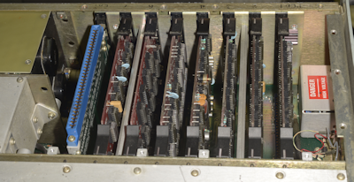
MA1101A Card Rack
Interestingly, Racal Supplied a very handy Extender Card in the card rack (see the photograph on the right). Admittedly this extender is required for certain specific diagnostics, but it did come in very helpful in this case. The Timing Circuit card is fourth from the right in the photograph. The circuity from which the 16-second delay is derived is self-explanatory from the schematic and I was able to verify that all aspects of the circuit were working ... with the exception of the driver transistor responsible for powering the fan-control relay. This transistor is driven by a bistable multivibrator configured from one half of a CD4001 (quad NOR). The problem was that with the driver transistor removed the circuit functioned perfectly. With the transistor fitted, the output of the Bistable to which it was connected remained high at the time when it should return to a logic zero. Changing the chip did not resolve the problem, nor did replacing the transistor.
Exacerbating the problem was the fact that the fault was intermittent ... occasionally the fan would switch off, but application of an oscilloscope probe to the bistable circuit was enough to switch it on again. I suspected the relay, but since getting to it would require dismantling the PSU, I decided to make doubly certain. I contrived a visual indicator ... an LED and a resistor in place of the relay. Complicated stuff! With this, I was able to confirm that everything on the Timing Circuit card was working. The LED illuminated as soon as the preselector started tuning, and remained on for a period of approximately 16 seconds once it had stopped tuning. Thus the relay was confirmed as the culprit ... but why?

Fan-Control Relay
What could go wrong with a relay? According to the PSU schematic, the back-EMF diode is integral to the relay, but measuring the resistance of the coil in both directions was inconclusive. Also, failure of the diode would invariably result in destruction of the driver transistor, and I had proved that the transistor was not damaged. Getting access to the relay was a task in itself. The PSU is simply a sheet of steel folded into a U-shape with a heatsink across the open end. The PSU PCB is mounted on the inside of this heatsink with the relay in the centre. I've never understood Racal's love affair with exposed wire fuses. These can be found in the RA1795 PSU, the RA1792 PSU, and now we find a row of them in the MA1101 PSU. Who do you know carries a reel of the appropriate wire for when these blow?
As it was, all the fuses were intact. I had to remove a couple of captive nuts in order to ease the heatsink/PCB out of the PSU before removing the relay. This turns out to be an encapsulated high-voltage reed-relay by Pickering Electronics, who are still in the business of designing and manufacturing reed-relays. Unfortunately this particular relay looks like it is no longer available ... it is after all 50 years old. According to the datasheet, the life of the relay drops off significantly as the power it has to deliver increases, so it was entirely feasible that it had simply come to the end of its life.
Naturally, looking through my box of miniature relays, I didn't have anything like it, or that I was comfortable with connecting to 120V. I did find a 12V relay about double the size that I figured would fit in the space, at a squeeze. I attached some wires and a back-EMF diode and verified that it worked. However in order to check if it would work in practice there was no alternative but to fit it for real. Mounting it on the board required some ingenuity and re-assembling the PSU was not an easy task. It worked! The blower came on as soon as the preselector started tuning and switched off 16 seconds after tuning stopped. I tried it again. It still worked. I initiated tuning at different frequencies between 2MHz and 30MHz. I verified that below 2MHz the preselector switched to Wideband. Now it was time to re-fit the fan
There isn't anything in the manual which states which direction it blows, but I figured that it drew air out of the unit. In that configuration the moving part of the fan would be towards the outside, in close proximity to the grill. With the fan fitted in this manner, it made a terrible racket which I concluded was due to partial contact between the fan rotor and the grill. This was despite the presence of spacers. Slackening the four screws eliminated the problem. I replaced the four spacers with slightly longer ones and that cured the noise problem. It is possible that age had resulted in increased lateral movement to the extent that the rotor started making contact with the grill and the incurring friction increased the current and thus had a detrimental effect on the life of the relay. Its just a theory.