A much-modified R1155
18 minute read
September 2021
Never one to turn down a challenge ...
This month I did something that for years I had said I would never do.
Some time ago, probably back in 2019, I was contacted (by telephone) by a gentleman who told me that he had an R1155, and asked if I would be able to check it over and get it working. This sort of enquiry always merits a lot of questions on my part, afterall, I need to know exactly what I am about to be faced with. As far as WW2-era receivers are concerned, the R1155 is the one most likely to have been brutally modified. It turned out that this was one such example ... that he and his Grandfather had worked on in the early 80s or thereabouts. I said that I would have to see the radio ... I suggested photographs, and that was the last I heard ... until earlier this year, when I received another call from the same gentleman. This time he had more than one 1155 and was going to be passing my way. A look at the real thing is always better than a bunch of out-of-focus photographs ... and I've been sent more than a couple of those over the years!
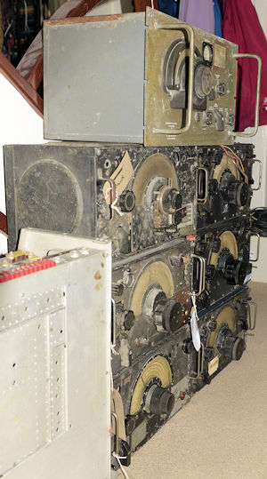
Six R1155s and one R1132A
On his way, he had managed to pick up two more 1155s and an R1132A! I had a look inside the 1155 that he was so keen for me to 'restore'. It's at this point that I wish I had taken a photograph. As expected, the DF circuitry and Master-Switch had been removed to make room for the obligtory PSU and audio amplifier. It isn't unusual to find the DF compartment on the rear of the BFO empty. I've even seen a couple of 1155s where the rear compartment has been removed! But in this one, the entire BFO/DF module had been removed. But not only that, all the valves were different! I didn't think too much of it at first, since one often finds a metalised ECH35 being used as the mixer-oscillator; an entirely valid substitution, since it and the VR99 are essentially one and the same. However closer examination revealed that ALL the screening-can bases had been removed too.
Ironically, the V4 (VR99) position was actually empty and all the other valves with the exception of the VI103 were Octal-based but with a metal skirt, making them slightly wider ... hence why the bases for the screeing cans had been removed. But why go to the bother of changing literally every valve when the original valves were so easy to come by? As far as the other 1155s were concerned, two were deemed candidates for FULL refurbishment, including DF circuitry and two were prompty marked as donors. As for the 1132A, albeit a tad grubby, it is complete and a viable restoration project.
In truth, I was so intrigued by what I was seeing, that I simply had to find out just what had been done to it. So, I decided there and then that I would accept the challenge to 'raise to life' this remnant of a once iconic WW2 receiver, albeit now far removed from its original form.
So, as well as being contracted to 'restore' the much-modified R1155, I also agreed to produce two fully functional examples from the other four. YIKES!
A very unusual tuning dial
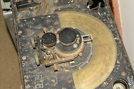
In the photograph above, the 1155 in question is the one on the left in the middle row. Sharp-eyed readers will see that the 'Magic-Eye' is situated on the left, where the Meter Amplitude control should be. The receiver above it is sporting a most unusual tuning dial/mechanism. If anyone can identify it (left), I would love to hear from you.
I set about identifying and testing the valves that had been fitted.
The RF amplifer and two IF amplifiers were W76s, all of which tested good on my VCM163. However, the original audio stage was now a DH76 and that registered a serious internal short-circuit. The PSU rectifier was a 5Z4G, which tested good and the obligatory audio PA was a 12A6 which also tested good.
As you can see, there is a theme developing here; none of these valves have 6.3V heaters.
In fact, with the exception of the 12A6, the others, the W76 and DH76 are from an era when domestic receivers did not have a mains transformer, when the HT was simply rectified mains and the heaters were all connected in series with a 'mains dropper' ... just like televisions up until the 1970s!
Turning my attention to what constituted a rather lethal power supply. Although it did have a couple of fuses, one had been shorted out with a length of wire! The transformer was of considerably better quality than others I have dealt with. Interestingly as well as a 5V winding for the 5Z4G, it also sported a convenient 12V heater winding. I had to wonder if this was the reason for the choice of valves? We live in an age where the internet gives us access to millions of archived documents. Everything you ever wanted to know about the R1155 can be downloaded for free. This was not the case back in the late 70s or early 80s when I believe this receiver was modified. However, service sheets for hundreds of domestic receivers were readily available. So either our intrepid enthusiast chose valves to match the only transformer he had at hand, or he chose to re-model the 1155 along the lines of a receiver he was familiar with?
Examination of the heater wiring revealed something interesting. There apeared to be two circuits. The W76s, DH76 and 12A6 were all in parallel, whereas the original VI103 and V4 were in series, across the 12V winding. This logically suggested that the missing Mixer/Oscillator was very likely an original VR99 or equivalent. However this arrangement would only work as long as the heater currents for the VI103 and VR99 were the same ... which they are, both draw 300mA.
As it stood, I could simply pop an ECH35 or equivalent in for V4 to complete the valve line-up but I was having difficulty figuring out the actual circuit since there were so many broken and loose wires. So I made an executive decision. I would re-build the R1155, as close as possible to the original using the current valves. This was going to be interesting.
In order to do this, I realised that it would actually be convenient to re-fit the missing BFO, since V7 also forms part of the AVC circuit. I was still wondering why someone would remove the BFO. Then I remembered a remark that the owner had made. He siad that his Grandfather had told him that the switch in the bottom left corner of the 1155 had been for a heater which the operator could switch on when it got cold in the aircraft. At the time, I simply pointed out that the switch in question enabled the BFO. In hindsight, it isn't difficult to see how someone with minimal knowledge of terms relating to 'wireless reception' in the 1940s would assume that 'HETr. ON' meant 'heater on' ... thus, the BFO had been stripped out.
Re-fitting the BFO however, required some re-thinking regards the heater wiring. My intention was to use a 12K8GT as the mixer/oscillator since it was from the same 'family' as the W76 and DH76. Although all three valves are designed for a series heater configuration, their respective heaters are all conveniently nominally 12V or 13V. I could then simply wire the VI103 heater in series with the BFO heater. However, that raised another issue, which those familiar with the R1155 will be familiar with ... I would not be able to use an original VR101 since it and its commercial equivalent, the MHLD6, have a heater which draws a whopping 635mA. Put that in series with the VI103 (aka Y63), with its 300mA heater, across the 12V winding and you would get 8V across the VR101 and 4V across the VI103. However, there is a simple solution ... replace the VR101/MHLD6 with a DL63, which is a direct equivalent, but with a 300mA heater.
So, now I had a plan ...
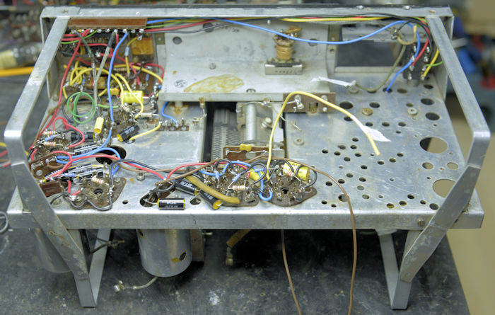
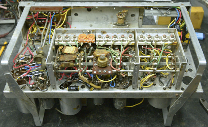
Armed with the confidence of having previously stripped down and re-built no less than ten R1155s, I set about gutting the latest example. As well as the Master Switch and BFO, the entire Jones Panel was also missing. The PSU and Audio Power Amp would be re-built in a separate box and it was my intention to use P1 of the Jones panel to do what it was intended for ... supply the HT and Heater supplies, the Antenna connections and Audio output.
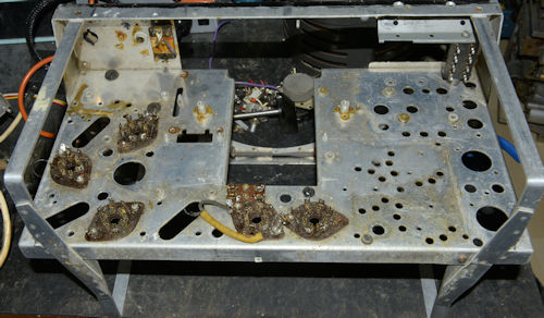
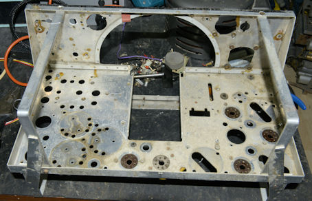
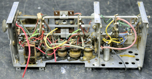
Above: Two views of the stripped down chassis. Note that P1 in the Jones Panel area has been fitted already. The chassis is yet to be cleaned.
Normally, when re-building an R1155, one of the first things that I do is re-stuff all the tall chassis-mounted capacitors. However, on this occasion, the plan was to fit individual capacitors as required under the chassis. Any chassis mounted capacitors removed from the chassis would be retained for re-building the two fully working 1155s at a later date. However cleaning and refurbishing of all parts to be re-used went ahead as usual. Below is IF-Transformer L19.
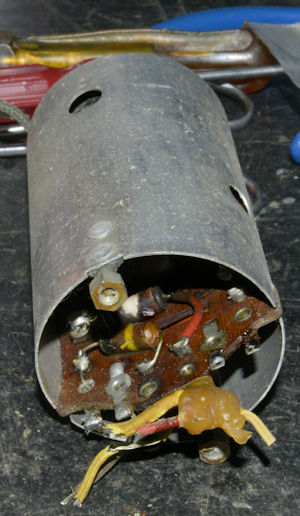
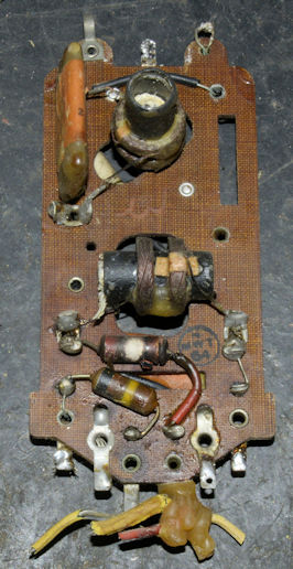
Above: The mass of wax clinging to the wiring was ominous. The 2K2 resistor is in the anode circuit of V4, and the fact that it was clearly 'cooked' would indicate that something had failed around V4. Maybe that was why V4 was missing when it arrived? Interestingly, the resistor still measured close to 2200 ohms, but it had clearly got very hot and melted the wax on the wave-wound inductor above it. This is the source of the pooled wax. At time of testing, the vertically mounted capacitor at the top was found to be the wrong value. 140pF had been fitted where 300pF was called for.
Above: The Coil-Box during refurb: Fortunately, much of the wiring in the coil-box was not the sort that disintegrates. There are four chassis-mounted 100nF capacitors which I re-stuffed. I figured it was simpler to do that than try to mount modern ones in their place. Note that L1, the dummy loop, was missing. Since this receiver will not be re-built with DF capability there was no requirement to re-fit it. When removing the coil-box from the chassis, it came as no surprise to discover that the wiring to one of the wafers had been altered so as to connect the 'trailing' and 'fixed' antenna inputs together. This is a very common mistake which actually compromises the performance of the input preselector. Shorting the two inputs together actually connects the primaries of two tuned transformers in parallel.
Above: It's a good feeling when you get round to putting it all back together. The replacement BFO is already on top, as are L19, L20, L21 and L23. I fitted the correct audio output transformer and the 9-way distribution tag-board. Note that the individual 100nF capacitors and a couple of 0.5uF capacitors are fitted close to the chassis, under the wiring wherever possible, thus keeping things tidy. The coiled green wire on the left will be cut off later as it is associated with the DF circuit and therefore not required.
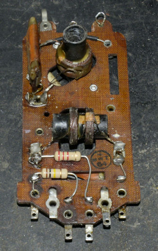
The resistors around the valve bases, are either in the respective anode circuits or provide the respective screen-grid bias. All of these had been changed such that their values did not match the 1155 schematic. All the 'original' 1155 valves have a typical maximum Anode voltage of 250V and Screen voltage of 100V. All the 'new' valves had a much lower maximum Anode voltage of 175V with a Screen voltage of 100V. So why had all the screen bias potential dividers been altered? Maybe an attempt to maintain the 100V on the Screens whilst the Anode supply was reduced? In reality, the level of volts on the Screen is not that critical as long as it is (in this case) not greater than 100V. Thus, the potential dividers were replaced with original values. The typical HT supply for an R1155 was 217V, so there never was any danger that the maximum Anode voltage was ever exceeded. I on the other hand, would need to ensure that the maximum Anode voltage on any of the 'new' valves did not exceed 175V. A precarious network of dropping resistors had been employed for this purpose, but I had other plans for the PSU.
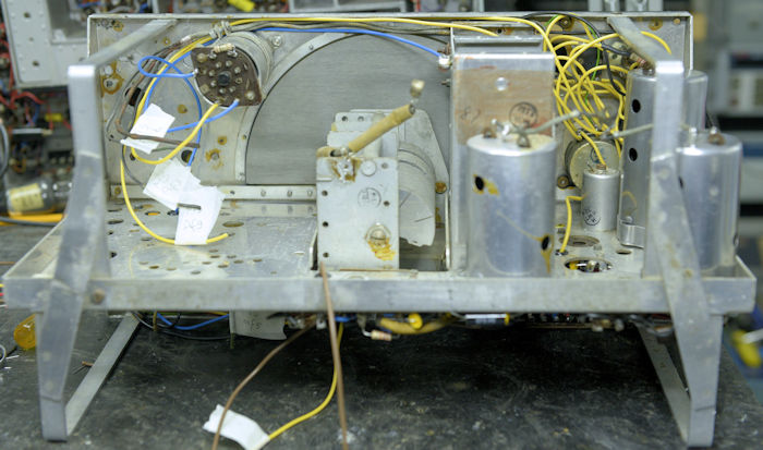
Above: I've re-fitted the dual-gang 'Increase Volume' control and the 'Hum Filter'. I fitted the latter since the assembly embodies several components which are crucial to the AVC circuit and overall biasing. Although not immediately apparent in this photograph, the trimmer capacitor in the BFO has been removed and replaced with a front-panel-mounted one of same value; fitted where the Meter Balance control would normally go. This will allow the user to adjust the BFO when resolving SSB without need of a screwdriver. At this point, the wiring it not exactly tidy. The Master Switch is yet to be fitted.
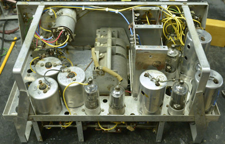
Above: Two views of the inside of the 're-born' receiver. The cluster of 2.2uF capacitors top right in the right-hand photograph would normally be chassis mounted block capacitors. It worked first time. No nasty surprises. Despite the use of completely different valves, the alignment process was carried out without any issues. AVC and Manual gain control worked pefectly and the audio into WW2-vintage Hi-Z headphones was very pleasing.
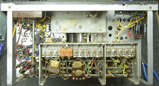
Above: Another view of the underside of the finished receiver. The inductor mounted on the underside of the main tuning capacitor is a remnant of the 'Athlone Filter' which is no longer required. It cannot be removed since it is actually soldered to the chassis! One thing to note, and I hadn't realised it until I started re-building this receiver, is that the valve pins in this set of valves are identical to those in the original set. It would appear that there was something of a 'standard' involved ... how convenient. The only minor issue encountered was that the intensity of the VI103 was so woefully low that it was barely visible even with the workshop lights out. However, a VI103 retrieved from one of the donor sets yielded a nice bright one ... see below.
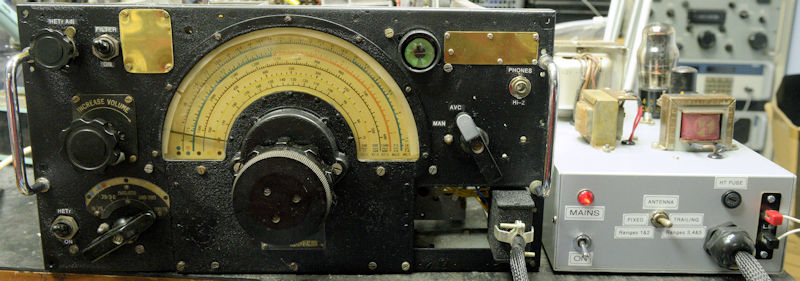
Something that has probably amused may people over the years might be the fact that the 'Volume Control' on the R1155 is labelled 'INCREASE VOLUME', which to some people might be taken as a tad patronising. However the words 'Increase Volume' are an accurate and implicit description of what it does. What you need to understand is just how it works. For a start, it is an asymetrical dual-gang control which actually performs two functions, but NOT simultaneously. In our re-born pseudo R1155 you will see the partially annotated Master Switch on the right, where the first two positions are labelled 'MAN' and 'AVC'. This is how it should be, although I have never understood why the first position was referred to as 'OMNI' and represented by a circle with a dot in the centre.
From A.P.2548A, Vol.1, Chap. 2 :
(i) ("OMNI") .Normal reception for communications purposes. The gain of the R.F. amplifier, frequency-changer and I.F. stages is manually controlled by a potentiometer R8(1).The AVC circuit is inoperative.
(ii) A.V.C. The automatic volume control operates on the R.F. amplifier, frequency-changer and I.F. stages. Manual volume control is by the potentiometer R8(2) which controls the audio input to the output stage.
The Tuning Indicator 'Magic Eye' only operates when the AVC circuit is active.
Now onto the power supply ...
All the major components in the PSU/Audio Amplifier were salvaged from the modified receiver. To be honest, the design, as it was, did not differ too far from what I ended up with ... only, my version (below) was not a death-trap.
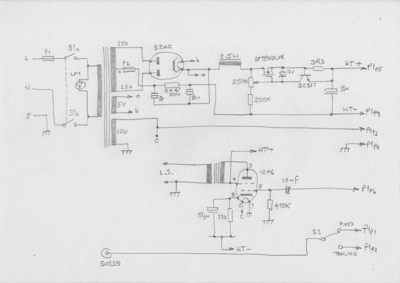
For a while, I pondered over a away to drop the HT down to something that wasn't going to over-stress the valves. As it stood, at the output end of the 2.5H choke, HT+ was about 230V, a voltage that any normal R1155 would be quite happy with. I thought about simply inserting a crude voltage dropping resistor, as had been done originally. I even considered using a couple of stabiliser valves. But the answer was right in front of me. I have been using something very similar to that in the schematic above in a variable High Voltage power supply for testing RA17 modules for the last ten years. It may be crude, in that since it has no voltage reference, the output will vary pro-rata with any input variation. But it works, and I was able to set the output such that the maximum voltage on the anodes of the valves was 175V.
The audio amplifier is based on everybody's favourite 6V6 circuit. Note that the input and output are with respect to chassis but the cathode circuit is connected to HT-. This is necessary since if it were connected to chassis, the current drawn by the 12A6 would have an adverse influence on the HT- line and thus impair the AVC performance, amongst other things.
The PSU/Audio box also supplies the respective aerial feeds to the Fixed and Trailing aerial inputs on P1p1 and P1p2 from a common aerial connector at the rear.
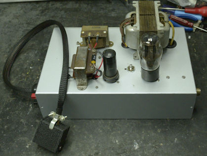
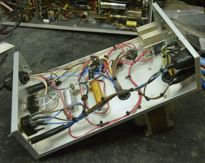
Above: Two photographs of the finished PSU/Audio amplifier. The MosFET can be any N-channel device capable of sinking 150mA. Note that it needs to be on a suitable heat-sink. The voltage adjuster control is mounted on the chassis between the 5Z4G and the 12A6. I cut the shaft down and filed a slot in it.
So there you have it. I finally did what for years I had said I would NEVER do ... work on a heavily modified R1155 to the extent that it still bears little resemblance to the receiver it once was.