Custom Interface Unit
6 minute read
A Dedicated Interface for the RA17, RA17L, RA117 & RA218
November 2012
This interface came about as a consequence of the fact that the RA218 was never designed to provide direct audio output to a loudspeaker. Instead, as part of the CJK configuration it was designed to deliver the baseband signal into a 600 ohm transmission line … although it does provide 1/4” jack sockets for local monitoring via headphones.
Design considerations: From each of the three receivers (RA17 MK1, RA17L & RA117), the interface requires a 100KHz output signal and a 3mW DSB baseband audio feed. The interface also serves to connect the aerial to which ever receiver is selected. A further function of the interface is to take the 1MHz reference from my MA259 and deliver it via cathode-follower buffers to up to four receivers.
Design considerations: From each of the three receivers (RA17 MK1, RA17L & RA117), the interface requires a 100KHz output signal and a 3mW DSB baseband audio feed. The interface also serves to connect the aerial to which ever receiver is selected. A further function of the interface is to take the 1MHz reference from my MA259 and deliver it via cathode-follower buffers to up to four receivers.
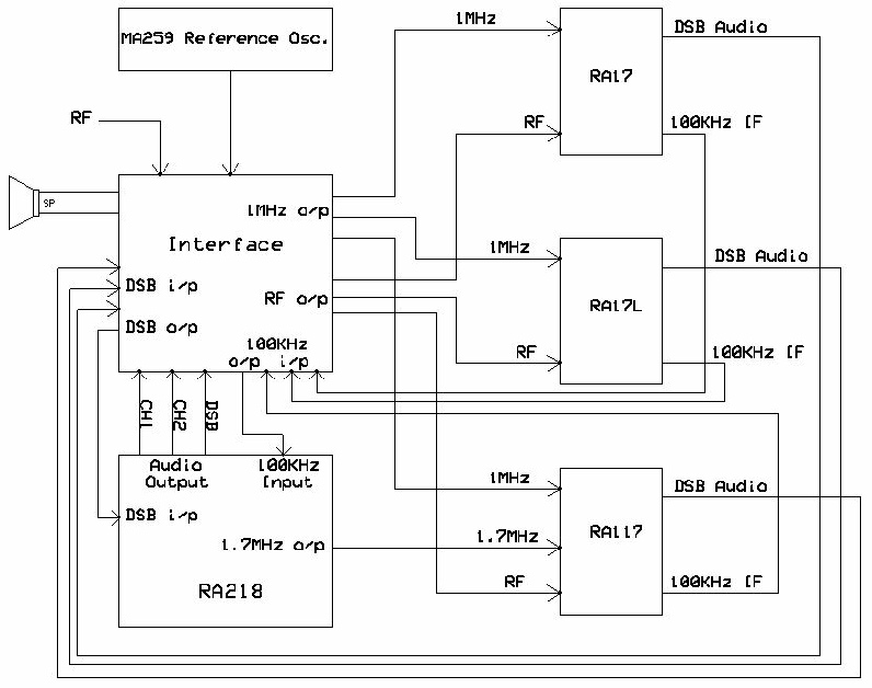
Concept block diagram
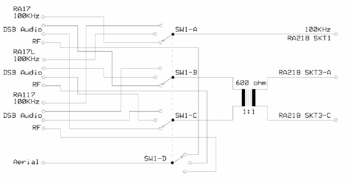
The Passive bit ...
The RF (Aerial) and 100KHz feeds are coax cable, whilst the DSB audio feeds are ‘twisted pairs’.
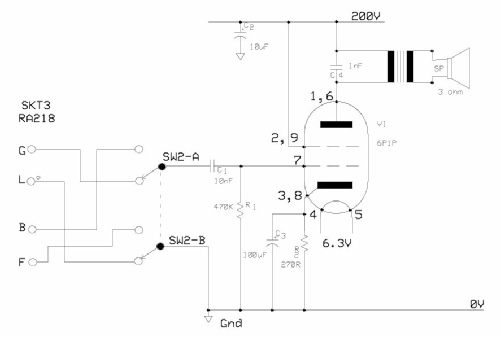
The audio amplifier … ‘Borrowed’ from the RA117 …
The RA218 provides two resolved audio outputs at SKT3 on the rear panel. I considered using a 6AQ5 to drive the loudspeaker but opted to use the Russian 6P1P which is ‘listed’ as an equivalent to the 6AQ5 despite the fact that it (the 6P1P) is a B9A device. I figured that the larger valve would be more robust.
SW2 selects the desired audio feed.
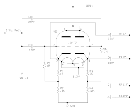
The 1MHz Cathode-Follower buffers … ‘Borrowed’ from the RA218 …
V2 and V3 are 12AT7s. Only half the circuitry is shown on the left since both halves are identical.
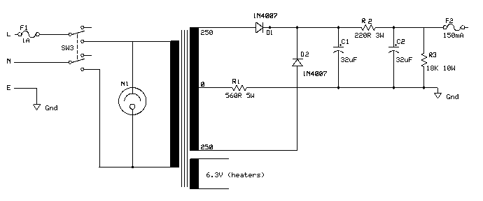
The PSU ... Keep it simple!
Although this configuration of full-wave rectifier imposes a higher load on the transformer, the actual load is very small, resulting in negligible effect. I found the transformer in my ‘junk box’ and found it to be extremely ‘generous’. Initial tests yielded 450V DC off load! … hence the inclusion of R1 (560R) and R3 (18K). R3 serves to provide a static load before the valves conduct during which time the maximum voltage at F2 is in the region of 265V. This drops to about 205V when the valves have reached their operating temperature.
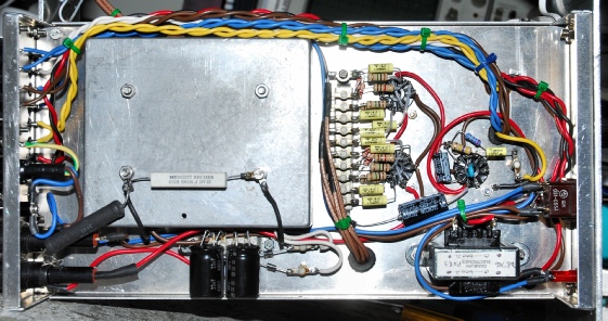
Left: I built the interface around a standard box from Maplin, mounted upside down as a chassis. The die-cast box serves to allow the mains transformer to be mounted below the top of the chassis. This was necessary since it would have extended beyond the upper edge of the front panel.
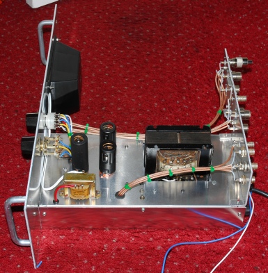
right: The loudspeaker is from an ex-PMR installation. The audio output transformer is one of the two that were removed from the RA218. With reference to the photograph above, note how the transformer is ‘sunk’ into the box … much like the mains transformer in the RA218 actually.
Left: The Interface, finished in Light Admiralty Grey and installed … The switches are deliberately sited to complement those on the RA218. I even opted to make the mains switch operate in the up position. It should be noted that when using the interface and the RA218 with the RA17 or RA17L it is necessary to ‘swap’ the sidebands. This is because the RA218 was designed to complement the RA117 which is Quadruple-Conversion. The RA17 and RA17L are only Triple-Conversion receivers and thus the sidebands are reversed. I filled the space above the RA117 with a vented 3U panel, also finished in Light Admiralty Grey.
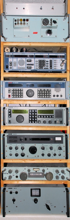
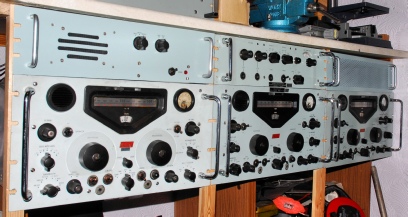
The Rack
This is my MA259 (serial number N1) Frequency Reference.
This is an Adret 740A, 100KHz - 1120MHz signal generator which came to me with a whole raft of faults. Miraculously, I was able to repair it without a full set of diagrams. Fortunately, I now have 99% of the circuit diagrams.
This is my RA3701 … Racal’s HF receiver of the 1990s. The previous owner was convinced that it was faulty since none of the IF filter bandwidths could be selected. This was because the ‘settings’ on the processor board had been ‘wiped’. I found the password for this on a Japanese website and Danny Higgins, G3XVR provided the filter settings.
The RA1792 … Racal’s first uProcessor-controlled HF receiver from the early 1980s. Both of the custom LCD panels were u/s. But apart from that the receiver was and still is in good order. I obtained a completely new front panel assembly, complete with Italian-made replacement LCDs.
The legendary RA1772 … from the early 1970s … often described as the finest HF receiver ever produced. This came with several faults. The two major ones being a broken AFC switch (now replaced) and what was described as an AGC fault. The latter turned out to be a faulty resistor in the PSU which was affecting the -7V line.
The quirky and much maligned RA1217 … the rack-mounted version of the RA217 and in the late 1960s, was Racal’s first transistorised HF receiver.
The MA197 Preselector. The world’s largest 8dB pre-amp! This unit allowed any connected receiver to use the same antenna as a 1KW transmitter PROVIDED the preselector (and the RX) were tuned to a frequency HF or LF of the TX by a factor of at least 10% of the transmitter frequency … well, that’s the theory!