18/24 Vertical
6 minute read
Experiments with a vertical for 18MHz and 24MHz
March 2006
This is what I like about Amateur Radio . . . Being able to look at to what for many would be a pile of scrap metal, and see a potential project. That’s what happened last year (2004). However It’s only recently that I have finally done something about it.
Once upon a time, a friend of mine had the misfortune of having his 15m mast topple over. Actually he has had this misfortune on no less than three occasions but that’s another story ...
On one of these occasions, a rather nice 10m beam was sadly written off and the debris stowed at the side of the ‘garden’. Last year, whilst helping my friend to clear his garden of various items of detritus, we unearthed the remains of the 10m beam and I instantly thought “I could turn that into a multi-band vertical”. Having just made a multi-band dipole for 30m thru’ 160m employing coaxial transmission-line traps, I was already geared up for the job. The original plan was to employ a coaxial transmission-line trap, until I found a design for a 10m/15m Trap Vertical in the ARRL Antenna Handbook. This design is simpler, forming the trap out of a few turns of heavy gauge wire and a length of coax as the resonating capacitor across the inductor. Although more lossy than the transmission-line trap, this design is mechanically less complex and is very simple to implement into a dual band vertical. The coil is wound on a length of 25.5mm grp tubing and the coax, RG316/U (used because I have miles of the stuff) is fed up the inside of the tubing and connected across the coil. See figure 1, below.
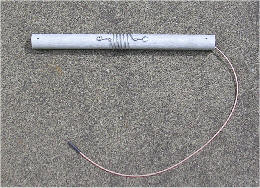
Fig. 1 - 25MHz Trap
I still had the length of ‘hard-line’ (FSJ 2-50) in place, that used to feed my modified HF6-V, and with the ‘Bypass’ connector on my Vectronics VC-300 un-used, I decided to make an antenna for 17m and 12m. Both these bands are very narrow, only 100KHz, so once the antenna dimensions had been fixed, no tuning would be required. This kind of antenna requires radials and two on each band would double as support guys. Although the initial tests were carried out with only one per band, the results were encouraging, with the resulting VSWR across both bands not exceeding 1.7:1. I decided to press ahead with the construction.
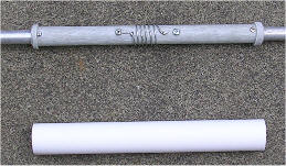
Fig. 2 - Trap Enclosure
One option was to leave the trap inductor exposed, but since it is wound closely onto the tubing, it would inevitably be compromised as moisture collected between the turns. The second option was to simply weather-proof the inductor by applying self-amalgamating tape. This too was dismissed since I anticipated the possibility that the tape itself would have an effect on the inter-turn capacitance. Therefore I opted to house the trap assembly inside a 2-inch length of plastic piping. See figure 2, right.
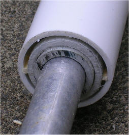
Fig. 3 - Matchsticks!
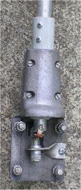
Fig. 4 - Base
To make the enclosure, I made rings from 31.7mm grp tubing to support the plastic tubing at either end. As can be seen from figure 3 on the left, the inside diameter of the plastic pipe is still greater than 31.7mm. However pieces of matchstick fitted into the gap at four positions resolved this issue beautifully, and the excess gap was then filled with epoxy resin. Now to make the mounting bracket ...
It’s a good job I rarely throw things out (much to my XYL’s annoyance). Back in the days when we had a viable radio-based DX-Cluster network in Scotland, I had an ex-PMR UHF colinear on top of my main mast. This was ultimately condemned when in 2003, the winch cable snapped and the N-Type connector was ripped off. But I didn’t throw it out ... and a good thing too! ...
To insulate the antenna from the mounting bracket, I double sleeved it with two concentric grp tubes, 25.5mm and 31.7mm. The latter fitting nicely between the two halves of what was once the base of the UHF colinear. See figure 4, right. For the feed-point, I adapted what had once been the feed-point of the afore mentioned 10m beam. I opted to leave the bottom end of the antenna ‘open’. I figured that if water was to inevitably ingress above, where the sections interlock, then I’d best leave some means for it to egress.
Figure 5, below, shows the attachment of the four tuned radials. These, I made from yet more antenna wire salvaged from the massive wide-band RACAL antenna that I picked up back in 2003. The radials are electrically connected to the base by crimp ring terminals, whilst loops created using mini ‘D’ clamps, allow the radials to double as guys by transferring the strain to the ‘U’ bolts attaching the base to the mounting pole ... Which is actually 2 of the 3 boom sections from the stricken 10m beam!
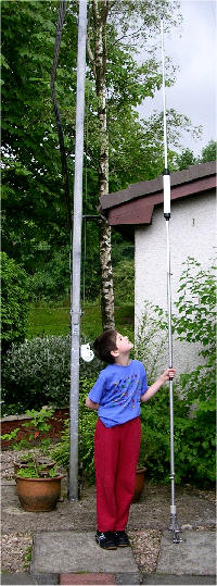
The photograph below right shows my (nearly) nine year old son Mark, holding the finished antenna I decided that the antenna should be fed via a twin-choke balun so as to minimise feeder radiation. A short length of grp tubing acts as an insulator between the pole and the antenna, thus minimising any unwanted resonance.
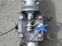
Fig. 5 - Radials.
The proof of the pudding, they say, is in the eating. So how does the antenna perform? As luck would have it, within days of installing the vertical, the HF bands were all but wiped out due to sun activity. However, on receive, initial tests had already indicated that in general, there is little difference between it and the Cobwebb, which is at twice the height.
It’s funny how things turn out. Now in August 2006, I still haven’t worked anyone on the 18-24 vertical. But then again, that’s because I haven’t tried yet. I have been engaged in other projects, which is what I love about this hobby ... and I get a real kick out of making things.
But how does it perform?