Spectrian PA for 13cm
6 minute read
More Power on 13cm!
July 2006
An ‘opening’ to Sweden on 13cm prompted a re-evaluation of my 13cm transverter. Ideally I needed more power. Initially I looked at discrete devices with a view to building a PA but then I was pointed in the direction of someone who had a couple of small PAs for sale. I made them, what I considered was a reasonable offer for the smaller of the two, a 10W amp. My offer was ignored, obviously not enough. Ah well! ... Good job really, because a few days later, I discovered the Spectrian single-board 60W PA ... and within a week I had obtained one!
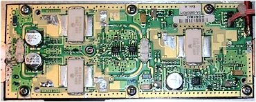
Spectrian 60W PA, 18dB gain
It has to be said that these boards are beautifully made. They appear to be constructed on a ceramic filled laminate, which is bonded directly onto a heavy copper heat-spreader which itself is gold-plated. These boards run from a single 26V supply and are only about 14% efficient . . . . But that is acceptable for a Class-A amplifier.
I decided straight away that the way to integrate the PA into the transverter was to adopt the same ‘back-to-back’ approach as employed in my 300W HF Linear. The Spectrian board provides a means of monitoring the individual Drain currents, and also the substrate temperature. However, although I intended to make use of the current monitor voltages from the outset, I initially opted for a mechanical thermostat to switch on any fans. The latter turned out to be an un-wise decision. The basic transverter had no problem in driving the amplifier up to a combined Drain-Current of 14A. At 14% efficiency this equated to a power output of 50W for 365W DC input, implying that 315W was thus expended as heat! The heatsink got very hot, very quickly (no fans yet). As luck would have it, we had another opening to Scandinavia and I had my second ever 13cm QSO, this time with Carl, SM6HYG who gave me a 59+++ report ... So I was rather chuffed! The problem with the mechanical thermostat is that there tends to be a 15 degree hysteresis involved, meaning that if the switch closes at 35 degrees C, it will not open again until the temperature has dropped to 20 degrees C. Well, It never gets that cold in the shack! So the fans never went off once switched on. I was not comfortable with using a 60 degrees thermostat so I decided to make use of the on-board temperature output voltage.
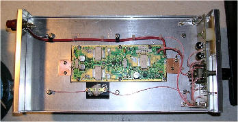
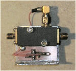
The photograph on the left shows the final build of the amplifier with the fan control PEC taped to the front panel PEC. Note the copper sheets at either end of the PA board. I’m not sure what the preferred method for getting RF on and off the board is. Such is the heat dissipation quality of the copper spreader, that it is virtually impossible to directly solder to the ground-plane, thus I devised a method whereby the coax braid is soldered to a copper sheet which is screwed down at the appropriate point adjacent to the board. The Coax inner is then soldered to the PCB track and copper strips 1mm thick are screwed down so that they overlap the edge of the board so as to give a solid RF grounding. This creative approach appears to work rather well too.
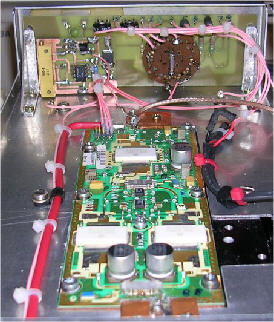
Following on from my experiment with my 23cm transverter whereby I augmented coax relay isolation by adding a PIN diode in front of the pre-amp . . . . I did the same for my 13cm transverter. And yes, that is a new MK2 DB6NT transverter pictured right! I recently treated myself and invested in the kit version of the latest 13cm box. The rather convoluted semi-rigid cable runs are historic and not having enough spare, I opted to leave them as they are. This time the PIN diode is shunt configured and is an HP-33123A. I made up a DB6NT-style sequencer with an additional output to drive the diode and stuck it on the mounting plate for the diode. When the PTT is pressed, the transverter goes onto transmit. The 12V (nom) TX output from the transverter asserts the sequencer which actuates the CX-520 coax relay and at the same time biases the PIN diode hard on. Finally the sequencer enables the Spectrian PA by applying 12V (nom). Below are two views of the PIN diode assembly.
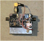
In my haste to mount the diode, the complete assembly ended up higher than the box itself, so I had to punch a hole through into the PA compartment for the top SMA connector to poke through ... A wee bit embarrassing, but acceptable. The performance of the MK2 DB6NT 13cm transverter is superb and probably doesn’t need an external pre-amp for troposcatter work.
13cm/60W left - 23cm/30W right
whilst the TX output easily drives the Spectrian board up to a final Drain current of 15A. The fan control PEC is set for the two fans to come on at 37 degrees C and go off again around 33 degrees C ... much more acceptable! The meter and front panel controls allow me to monitor the Driver and Final bias currents and an additional red LED comes on to let me know that the temperature has exceeded 35 degrees ... As if it were possible to ignore the fans!
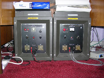
Finally, big amplifiers need big power supplies. Gone are the days when solid state equipment all ran off 12V. Here on the right is a view under one of the desks in the shack. These brutes started life in the 1970s as 24V MoD battery chargers. Only the cases remain though. The one on the left is the 26V/20A PSU for the 13cm PA. The one on the right is the 48V/20A PSU for my home-brew 300W HF PA. Both PSUs employ soft-start to protect the house mains wiring, hi! hi!