The Racal RA117E
14 minute read
January 2015 ... The One Transister Radio
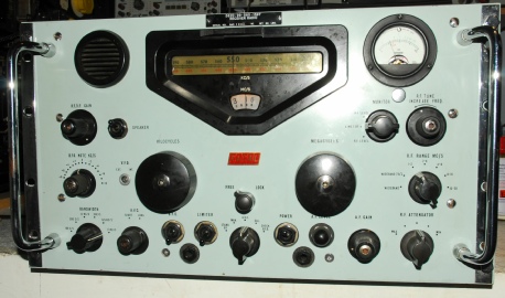
RA117E N0586 was given to me as a non-working receiver. Its previous owner generously passed it my way in the knowledge that I would almost certainly find the fault that had eluded him for a very long time. Little did he know, but I was about to identify not one fault but no less than thirteen faults … four of which had been with the receiver since it was manufactured back in December of 1965! I decided that this would be my New Year’s treat … get the ‘One Transistor’ Radio working. It was ‘stone deaf’ and only occasionally was it possible to receive the strongest of local MW signals. The logical approach was to strip it down to its individual modules and test each one in turn after refurbishment. That way, I would be sure to come across the illusive fault.
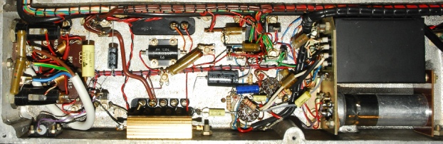
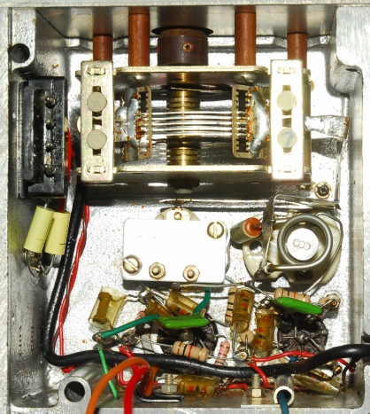
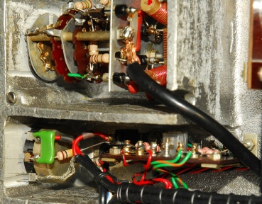
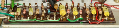
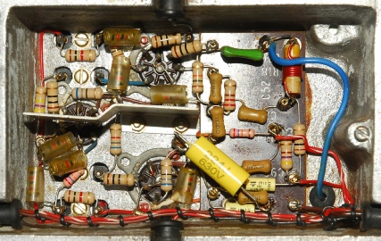
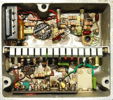
Unlike my plain-vanilla RA117, this E-variant had already received the approved PSU resistor upgrade. Note the black metal-clad resistors bottom left and centre and the large gold coloured 9K resistor.
The remaining carbon resistors and tubular capacitors were replaced with modern types and the PSU smoothing pack was re-stuffed with a pair of 33uF/450V capacitors.
Testing the PSU and audio circuitry is easy. The audio stages were working fine but a higher than expected voltage drop across the main smoothing choke, L80, indicated that something elsewhere was not right.
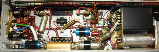
PSU/Audio compartment before and after
As with other receivers in the series, to remove the 1st VFO unit, the 2nd VFO must first be removed … although in this case it is not necessary to fist remove the lid of the 2nd VFO. The photograph on the right shows the refurbished front-end around V3 (ECC189). As I was stripping it down, I discovered that tag-8 on the valve socket was more ‘mobile’ than usual. This is the Cathode pin for one half of the Double-Triode, with two capacitors and one resistor attached. After clearing all the wires and solder away, I was able to simply pull the tag out of the valve base. It was completely snapped in two. The first fault. See the inset on the right. I was able to replace the broken receptacle with one salvaged from an identical socket. The circuitry around V3 was fully refurbished and re-tested. However, there was very little gain and the voltages around V3 were incorrect. This was identified as a faulty valve. Actually an internal short-circuit between pins 6 (a1) and 7(g1) … no doubt a direct result of the cathode (k1) connection becoming disconnected. The second fault. Having replaced the ECC189, the input circuitry performed as expected.
The VFO: The first thing that I noticed here was that pin 2 (g3) of V5 (6BA6) was NOT wired to ground. What was interesting also was that there was no trace of solder on the receptacle tag; meaning that this was a manufacturing error. The third fault. I fitted the missing link and finished refurbishing the circuitry. Without a bespoke test-set the 1st mixer cannot be tested off the main chassis, but the 1st VFO can be tested. However, something was wrong; the VFO was not running, yet all the voltages checked out. The problem turned out to be trimmer C77 (33pF) which was measuring a staggering 135pF when half-meshed. I removed the trimmer (an easy task) and found it to be filthy … covered in a coating of grime. The fourth fault. This was cleaned off with Isopropyl Alcohol and the problem resolved. C77 measured 33pF fully meshed and VFO-1 was aligned as per the technical manual.
There were no issues with this unit other than an observation which is worth noting. The manual for the RA117 contains an RA117E Appendix which states the following … ‘The RA.117E is a slightly modified version of the basic RA.117 …’.
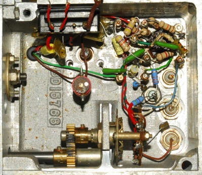
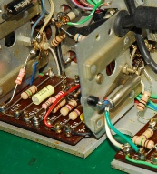
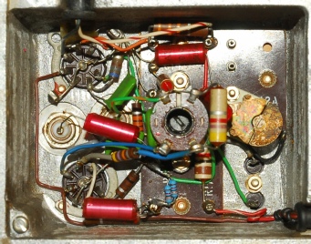
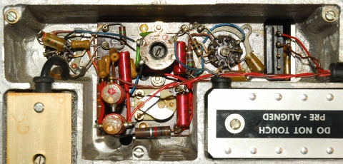
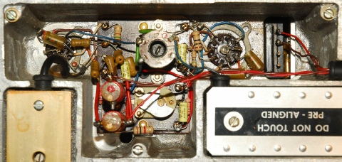
With reference to the photograph below left … note the three metal film (blue) resistors and the stud-mounted zener diode. This is the 2nd VFO in my RA117E and matches that found in the RA117A. The photograph on the right is that of a basic RA117.
While working on this, the second mixer, I encountered the tenth fault. See the capacitor to the right of the trimmer capacitor. This is C117 and it should decouple to ground the junction of R56/R66. However it was found to be across R56 instead. There is even a possibility that this is yet another manufacturing error!
Left: 2nd Mixer refurbished,
C117 in the right place.
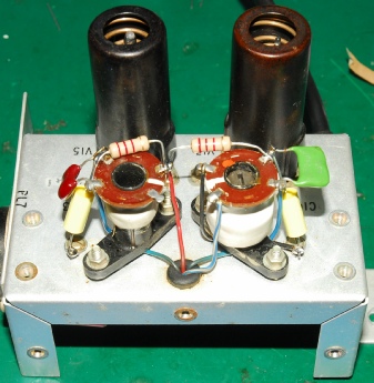
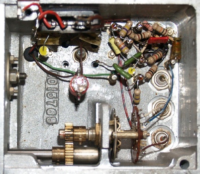
With reference to the photograph below left … note the three metal film (blue) resistors and the stud-mounted zener diode. This is the 2nd VFO in my RA117E and matches that found in the RA117A. The photograph on the right is that of a basic RA117.
2nd VFO in my RA117E
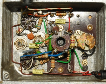
2nd VFO in my RA117
With the 1st and 2nd VFOs off the chassis it is prudent at this point to work on the Input Attenuator, the Meter Rectifier board and the Low Pass Filter on the output of the Harmonic Generator. Access to fixing screws for these items is hindered or impossible when the VFOs are fitted.
The fifth fault in this receiver turned out to be a broken 82pF capacitor in the Low Pass Filter on the input to the attenuator. No ‘hard’ faults were found on the Meter Rectifier or the Harmonic Generator LP filter.
Right: Attenuator and Meter Rectifier reinstalled.
Right: Attenuator and Meter Rectifier reinstalled.
The two VFOs were then re-installed. I honestly expected the receiver to burst into life. After all, I had found some major faults in the 1st VFO module. Still nothing. The 1MHz oscillator was running, albeit 50Hz low. When presented with a deaf RA17 (or RA117), A good place to look is on TP3 where there should be a healthy 37.5MHz signal every 1MHz when the 1st VFO is adjusted. I was only seeing a signal at one or two of the MHz positions. Checking the 37.5MHz drive into the Harmonic Mixer (V4, 6AS6) showed that the signal was not rich in harmonics. This was the sixth fault. This was resolved by carefully adjusting C7 on the output of the Harmonic Generator, (V2, 6AK5W). Now I was getting somewhere. I now had the correct signals on TP3 … AND the receiver was now working. So, on to the the 100KHz IF stage …
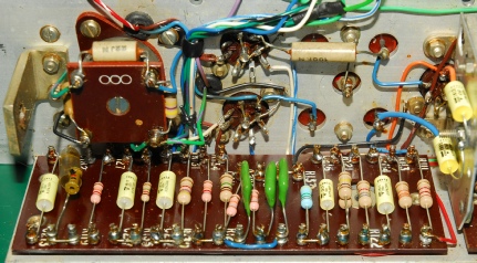
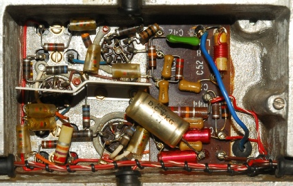
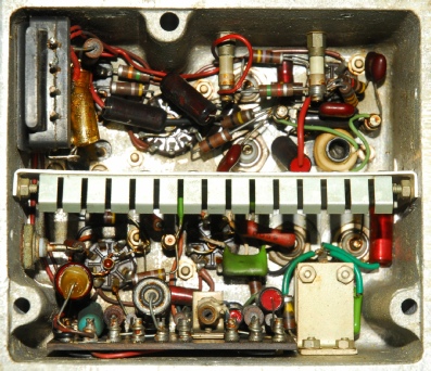
EA76 top left, Transistor VT1, bottom right
The 100KHz IF is home to the RA117E’s one and only transistor and is where the modifications are found. V24 had been previously replaced with a silicon diode but I re-fitted an original EA76 thermionic diode. I figured that since it had one transistor, it really ought to have a full compliment of valves! I don’t actually know what type the transistor is. I don’t want to damage it by extracting it from its clamp. But it is almost certainly germanium.
The RA117E no longer uses one half of V18 (6AL5) as an AVC time constant diode, so the wiring around V18 and the front tag-board is noticeably different.
Above: incorrect wiring. Below: Correct wiring.
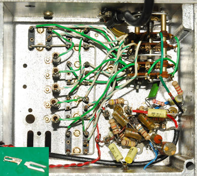
With the 100KHz module fully refurbished, including the BFO, the receiver was definitely working. But something was just not right with the AGC (or AVC as it was then called). Close examination of the AVC tag-board (right) revealed the problem. For a start there was no continuity between R102 (82K) and R123 (82K). BUT, R123 was connected to C239 (0.47uF). The latter was a legacy issue where a link should have been removed. The former was due to a missing link. Thus we have the seventh and eighth faults. Like the missing link in the 1st VFO, this was clearly another manufacturing error.
The tag board was re-wired and the AGC (AVC) now works perfectly.
The tag board was re-wired and the AGC (AVC) now works perfectly.
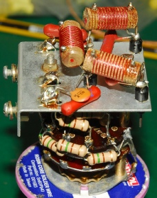
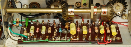
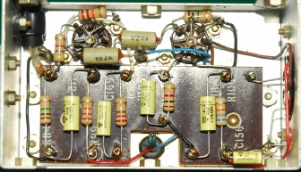
The receiver was now working well but there had to be a reason for the 1MHz oscillator being about 50Hz low, even with C2A fully un-meshed. As I refurbished this circuit I measured the value of key components but didn’t find any that were out of spec.
Note the two 20K resistors in parallel.
I did find that C11 was about 50% high in value but as suspected, this was not responsible for the frequency error. This turned out to be nothing more than a duff quartz crystal … The ninth fault … duly replaced with a shiny new one!
Note C2A now partially meshed.
While working on this, the second mixer, I encountered the tenth fault. See the capacitor to the right of the trimmer capacitor. This is C117 and it should decouple to ground the junction of R56/R66. However it was found to be across R56 instead. There is even a possibility that this is yet another manufacturing error!
Left: 2nd Mixer refurbished,
C117 in the right place.
Below: The Third Mixer Module … Nothing untoward in this little box. Fitting new smaller capacitors enabled me to tidy up the layout … hence the different component placement.
Before
After
I usually forget about the calibrator. Just when I think I’ve finished, I remember the little box that was disconnected right at the start. This unit was in pristine condition but got ‘the treatment’ anyway … and it was in the act of cleaning the valves that I encountered the eleventh fault. There were two 6BA6s fitted. V13 should be a 6BE6.
Correct valve fitted, unit refurbished and retested … perfect!
Correct valve fitted, unit refurbished and retested … perfect!
RA117E - Loose Ends
So what were the final two faults? Both were associated with the front panel. The twelfth fault was probably nothing more than a mistake by the previous owner. The RA117 series and the RA17C (North American RA17) have a three-position rotary meter selector switch. Associated with this is a meter adjustment potentiometer which is accessible through a capped hole beneath the meter. This pot is mounted on a bracket which is held in place by the same nut that secures the switch. In this case, the bracket was not correctly orientated so that one of the connections on the switch was shorting to the preselector metalwork.
The thirteenth fault was a bit more subtle. As mentioned earlier … The manual for the RA117 contains an RA117E Appendix which states the following … ‘The RA.117E is a slightly modified version of the basic RA.117 …’ And I’ve already pointed out that this RA117E employs the same zener-stabilised 2nd VFO as in the RA117A. The RA117E appendix lists all the components removed and added in the modification. One of the resistors that is removed is given as R144A. The problem is that there is no such resistor in the RA117 (or the RA117A). R144A (10R) is the resistor on the Loudspeaker Switch in the RA17 series. There is no such associated resistor in the RA117 but there is in the case of the RA117A where it is designated R160 (4R7). This resistor was present on the switch when it should have been removed. Thus, I have to conclude that the RA117E was actually ‘derived’ from the RA117A, not the basic RA117.
The thirteenth fault was a bit more subtle. As mentioned earlier … The manual for the RA117 contains an RA117E Appendix which states the following … ‘The RA.117E is a slightly modified version of the basic RA.117 …’ And I’ve already pointed out that this RA117E employs the same zener-stabilised 2nd VFO as in the RA117A. The RA117E appendix lists all the components removed and added in the modification. One of the resistors that is removed is given as R144A. The problem is that there is no such resistor in the RA117 (or the RA117A). R144A (10R) is the resistor on the Loudspeaker Switch in the RA17 series. There is no such associated resistor in the RA117 but there is in the case of the RA117A where it is designated R160 (4R7). This resistor was present on the switch when it should have been removed. Thus, I have to conclude that the RA117E was actually ‘derived’ from the RA117A, not the basic RA117.
... and finally
Contrary to the notion that the RA117 was the successor to the RA17 series; the two types were latterly manufactured ‘side by side’. From what I have read, the RA117 was designed to fulfil a US DoD requirement and the RA117E was manufactured for the Royal Navy and designated CJK as part of their new data transmission system; Radio Automated Teletype or RATT. It would appear that the RA117E’s role in this was actually seen as a ‘stop gap’, because as early as the mid 1960s the CJKs were being replaced with the newer ICS receiver designated CJA/CJC manufactured by Marconi.
However … enough historical supposition … The sensitivity for the RA117 series is the same as for the RA17L. I’ve never understood Racal’s pre-occupation with 1.5MHz when their receivers worked all the way up to 30MHz.
Thus the sensitivity is given as …
AM sensitivity at 1.5MHz … 18dB S/N for 3uV, 30% 1KHz modulation.
CW sensitivity at 1.5MHz … 18dB S/N for 1uV.
Fully refurbished and realigned, RA117E N0586 performs thus …
I can only put this staggering performance down to the quality of modern components. I have heard it said that towards the end of the type production run, RA17Ls (and presumeably RA117s too) were achieving S/N ratios in the order of 23dB. Thus it is possible that even in those days the improvement in performance realised, was a direct function of component quality.
A humorous irony with this particular receiver is that as a receiver manufactured at the height of the Cold War, it actually contains at least six Russian-made valves! I tested these against the EF93s and E180Fs that they are ‘copies’ of and cannot fault them, so they are staying.
However … enough historical supposition … The sensitivity for the RA117 series is the same as for the RA17L. I’ve never understood Racal’s pre-occupation with 1.5MHz when their receivers worked all the way up to 30MHz.
Thus the sensitivity is given as …
AM sensitivity at 1.5MHz … 18dB S/N for 3uV, 30% 1KHz modulation.
CW sensitivity at 1.5MHz … 18dB S/N for 1uV.
Fully refurbished and realigned, RA117E N0586 performs thus …
Frequency
1.5MHz
14.5MHz
28.5MHz
14.5MHz
28.5MHz
Mode
AM
CW
AM
CW
AM
CW
AM
CW
AM
CW
AM
CW
Sensitivity
29dB S/N for 3uV
30dB S/N for 1uV
28dB S/N for 3uV
29dB S/N for 1uV
23.5dB S/N for 3uV
25dB S/N for 1uV
29dB S/N for 3uV
30dB S/N for 1uV
28dB S/N for 3uV
29dB S/N for 1uV
23.5dB S/N for 3uV
25dB S/N for 1uV
I can only put this staggering performance down to the quality of modern components. I have heard it said that towards the end of the type production run, RA17Ls (and presumeably RA117s too) were achieving S/N ratios in the order of 23dB. Thus it is possible that even in those days the improvement in performance realised, was a direct function of component quality.
A humorous irony with this particular receiver is that as a receiver manufactured at the height of the Cold War, it actually contains at least six Russian-made valves! I tested these against the EF93s and E180Fs that they are ‘copies’ of and cannot fault them, so they are staying.
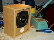
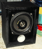
So impressed was I with the performance, I decided to give it a proper external loudspeaker, which was quickly knocked up from some spare MDF and a drive unit salvaged from a scrapped domestic radio. I gave it a coat of textured paint then sprayed it black.
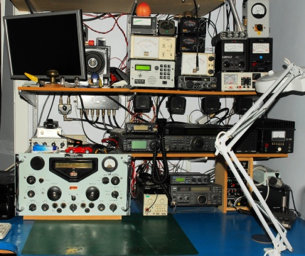
The RA117 and RA17C benefit from an improved audio stage … and this one really does sound good! The photograph on the right shows my new ‘boat anchor’ installed in the shack.