Restoration of another MKI Racal RA17
13 minute read
The repair and restoration of RA17 N659
March 2009
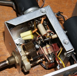
Well, Today I had a look at another RA17 for a friend (as suggested earlier), which turned out to be another MK1. I had been forewarned that a previous owner had attempted to ‘perk up’ the front end by fitting an ECC189 (as fitted in the RA17L) in place of the the usual E180F or CV3998. Since the ECC189 is a Double Triode and the E180F is a Pentode, the two are not interchangeable. I have been informed that this is a not infrequent error made by some people and the result is always the same . . . R28 and R31 burn out ... See the photograph below.
These two resistors are effectively in series with the E180F Anode. Substituting an ECC189 applies the 250V HT to the grid of V3B ... NOT a good idea! This mistake also over-stresses R35 in the HT/Heater filter circuit. R35 is subject to up-rating as per standard procedures and was due for replacement anyway. With all three resistors replaced, I reassembled the receiver and switched it on. To my relief, it actually worked ... but only just. Just like my specimen; sensitivity was low, the resolved audio was distorted and the front panel meter was evidently unserviceable. I decided to carry out a survey using the 2nd VFO unit as a test. There is a safety modification required to these units, so since it was going to be dismantled, I decided to ‘re-cap’ and ‘re-resistor’ it. The results were quite revealing. Of the nine resistors replaced, no less than three were high by at least 33% whilst a further two simply crumbled on removal! This gave me the excuse to recommend a complete refurbishment. The owner agreed ... But only after I had convinced him that I was NOT going to use old resistors and capacitors stored in his attic for the job!
Something else caught my eye. It wasn’t a fault, but a label, similar to one on the front of my RA17. At first glance, these might be mistaken for serial numbers but my theory is that they are inventory labels; and this is where it gets interesting; the serial number of this receiver is N659 (mine is N664) and the number on the front panel is SIN16377 (mine is SIN16379) I know that N659 came from a Civil Service department in Edinburgh, but as far as I am aware, N664 came with it’s previous owner from the South of England. What is evident here is that at least one of these RA17s is well travelled!
Having received the necessary permission to carry out a full restoration, the next module to get the ‘works’ was the 100KHz IF where, since the AGC was not working and the BFO tone was rough, I was fully expecting to find a whole host of faults. I was NOT disappointed.
Having received the necessary permission to carry out a full restoration, the next module to get the ‘works’ was the 100KHz IF where, since the AGC was not working and the BFO tone was rough, I was fully expecting to find a whole host of faults. I was NOT disappointed.
100KHz IF Strip and BFO
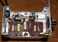
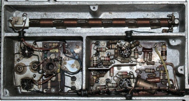
Something which I have to conclude is peculiar to the MK1 is the orientation of the Silvered Mica capacitors in the AGC circuit on the front tag board. Note that they, along with several resistors and a 10nF tubular capacitor are mounted horizontally as opposed to vertically. ALL diagrams that I have encountered show these mounted vertically. Also note the vacant tags on the other large tag board where in later models V24/(later MR8) would be fitted ... Evidence that the AGC circuitry did indeed undergo minor evolutions. Not shown here, but it might be worth a mention also. The MK1 does not appear to have been fitted with the simple 30MHz LP filter between the antenna connector and the input attenuator.
Now, back to the 100KHz IF ...
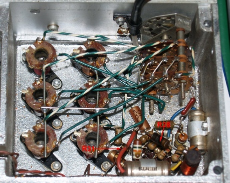
As with my RA17, the 100KHz IF was home to some of the worst cases of degrading components. Most of the large tubular capacitors turned out to be little more than high-value resistors and curiously, R90 and R91 (both 4K7) measured less than 300R!!, even though they didn’t show any outward signs of stressing. Also, it was noticed that the screening cans for V18 & V21 were loose. This was because someone had fitted a pair of the shorter CV4007s (6AL5W) instead of CV4025s. I therefore fitted a pair of new CV4025s.
Now, back to the 100KHz IF ...
As with my RA17, the 100KHz IF was home to some of the worst cases of degrading components. Most of the large tubular capacitors turned out to be little more than high-value resistors and curiously, R90 and R91 (both 4K7) measured less than 300R!!, even though they didn’t show any outward signs of stressing. Also, it was noticed that the screening cans for V18 & V21 were loose. This was because someone had fitted a pair of the shorter CV4007s (6AL5W) instead of CV4025s. I therefore fitted a pair of new CV4025s.
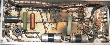
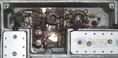
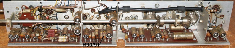 3rd IF (100KHz) before refurbishment
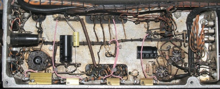
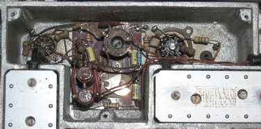
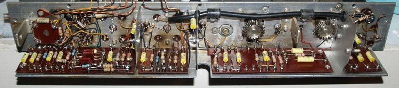 3rd IF (100KHz) after refurbishment
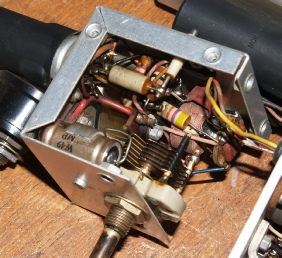
BFO before refurbishment
I will be honest here, unlike the 3rd IF, the BFO is a horrible unit to work on ...
But worth the time and effort in the end.
BFO after refurbishment
2nd VFO
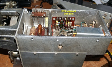
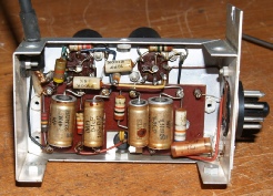
2nd VFO underside after refurbishment
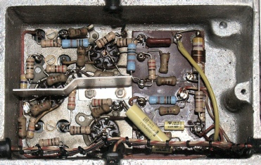
The 2nd VFO unit in this particular RA17 was not the hot bed of nasties that my one was. However the tubular capacitors on the small tag board were extremely discoloured and electrically unsound. 33% of the resistors in this unit were high in value by over 33% and two merely crumbled when removed. I suspect this high attrition rate may be due to high temperatures in an enclosed space.
Note: Replacing R76 with an RFC was an error and has been reversed.
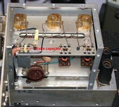
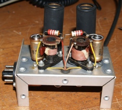
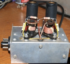
2nd VFO top side after refurbishment
The photograph on the right shows the extra 10nF capacitor that is added to isolate the 250V HT from one of the coax outputs at the rear of the receiver. Without this modification it is possible to expose the user to a nasty belt. Full details of this modification and the replacing of R76 with an RFC can be found in EMER E727.
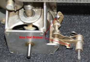
New Dial Brakes fitted
The photograph on the left shows the new bolt-on dial brakes. The fitting of which is detailed in EMER E727. In this instance, both older stick on pads had perished beyond usefulness. Also, the adjustment was so far out that only the MHz dial brake was making contact. The way to set these brakes is to loosen the two grub-screws on the rear pad and press it against the KHz fly-wheel with the brake OFF, Now apply the brake and temporarily tighten one of the grub-screws.
PSU and Calibrator
These before and after photographs of the PSU/Audio comartment speak for themselves. This particular RA17 had not had the 10K resistor (right of centre) replaced with a higher wattage version as detailed in EMER E727 Mod Instruction 1. Like in my RA17, the bulk of the burning has come from the enamelled 47R resistor in the centre. In line with EMER E727 Mod Instruction 19, all three wire-wound resistors have now been replaced with metal-clad versions which are bolted to the side-wall of the compartment. Since a 165R resistor was not obtainable, the value was made up by two 82R resistors. Both tubular electrolytic capacitors have been replace as have the two 220R resistors in the audio stages. Care should be taken when fitting C197 (100uF). Since this forms part of the -ve supply for the AGC, it’s +ve terminal is connected to the chassis. I have not found it necessary to replace the twin 32uF smoothing capacitor.
Before
Switch the receiver mode switch to ‘Cal’ and tune the KHz dial to 500 or thereabouts, until you hear the beat-note. Adjust the core (L75) nearest the 2nd VFO for best quality tone then adjust the core furthest from the 2nd VFO for maximum loudness. Check that the beat note can be achieved at both ends of the KHz scale. If this cannot be achieved make a small adjustment to L75. The tone should spontaneously appear when the core is correctly set. This method works every time for me.
After
2nd Mixer, 1MHz Osc. and Harmonic Mixer
2nd Mixer before
2nd Mixer after
This is the 2nd Mixer. I almost forgot to take the ‘before’ shot; hence the resistor on the right. This is a particularly tricky circuit to work on owing to the two end-mounted inductors bottom left. Their presence makes the removal and replacement of the 1K resistor (bottom) and several other components very tricky ... But not impossible. Keen not to incur the same spectacular burn out that I experienced with my RA17 I was opting to cutting the old components free then carefully unwinding the free ends from the solder tags. I found that the best way to achieve this was to heat the joint then grab the wire with hook-nose pliers and then just as the solder was almost solid, unwind it. This slightly unorthodox method allows you to remove the wire without incurring solder splashes.
Crystal Osc. & Harmonic Amplifier before
Harmonic Amplifier after
I got a bit carried away and forgot to take the obligatory ‘before’ shot of the Crystal Oscillator; hence why there is only a nice shot of the Harmonic Amplifier. It was after refurbishing this section that I became aware that something was not right. The receiver sensitivity would fluctuate spontaneously. I hate intermittent faults! Sometimes it is a good idea to walk away and only return with a fresh mind ... which is what I did. The root of the issue turned out to be C7, top left in the upper photograph. I was looking at it and noticed that someone before me had obviously been at it with a soldering iron. The PVC insulation on the wire to one of the terminals was clearly badly shrunken back. I gave the capacitor a tweak, or rather, I completely rotated it several times. This action completely cleared the intermittent drop in sensitivity. Past experience told me that some tiny shards of solder had been shorting out the vanes. This would not have caused any electrical damage but would have had a serious effect on the level of injection into the 30MHz LP filter.Then just to ensure it was clear, I gave C7 a good blast of compressed air.
Conclusions
As expected, RA17 N659 now performs beautifully. Interestingly, the similarities between it and my own one (N664) are not limited to serial and inventory numbers however. Both had broken Meter switches. Both had open circuit meters. Both had loudspeakers that although appeared to work, delivered extremely distorted audio. It is also interesting to note that in both receivers it was the 3rd IF (100KHz) unit which produced the worst degraded capacitors, although this might simply be because the 3rd IF is the unit with the most tubular capacitors. Statistically, 33% of the carbon composite resistors were high by a factor of at least 33%, reinforcing the need to replace the resistors as well as the capacitors. As was the case with my RA17, N659 was re-tested after each module was refurbished, and at each stage in the process the general receiver noise figure was seen to drop; a receiver full of leaky capacitors and out of spec. resistors produces a lot of unwanted pops and crackles.
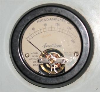
New Movement
As I said, the front panel meter was unserviceable. I don’t know why, but it now appears a common failure in RA17s. The good news is that it is not difficult to fit a new movement into the old casing. In this case I used a 100uA movement suitably shunted to bring it up to 200uA. The new movement had to be held in place with epoxy adhesive since the holes did not match. I also had to file a couple of notches in the scale-plate to accommodate the slightly wider movement (see right).
The fact that I have now come across two seemingly functional loudspeakers that produce extremely distorted audio is very curious indeed. My initial theory was that perhaps corrosion had formed between the pole-pieces and this in turn was interfering with the travel of the voice-coil. Having dismantled one of the loudspeakers, I am no longer convinced that corrosion is the culprit. Whatever the cause, the loudspeaker is not difficult to replace with RS Components part number 364-3357 being an excellent substitute albeit a higher impedance.
See the photograph on the left ...
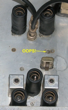
Finally, and proof that everything was done by hand back in the 1950s. I spotted this when giving the chassis a final clean. Clearly someone in the machine shop had drilled a hole in the wrong place. No Problem! Just fill it in and try again!