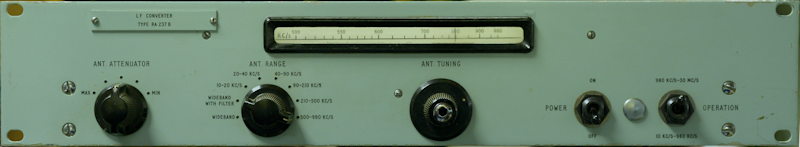
LF Converter Type RA237B
7 minute read
This post is part of the series 'Racal L.F. Converters':
 Although I have already written a couple of articles on Racal's other LF Converters ... the RA137 and the earlier RA37, I felt it pertinent to write a similar article for the RA117-specific RA237B.
Glance at the schematic for the RA237B and you could be forgiven for thinking that it is identical to the RA137 ... except if you dwell a little longer you will notice a nominally 2MHz crystal across the input to the Cathode follower on the output. Functionally, that is the only difference. The crystal acts as a rather crude notch-filter at 2MHz, to compensate for the fact that the RA117 (for which the RA237 is designed to interface with) does not have the same IF pass-band filtering as the RA17 etc. The notch is there to reduce the amount of 2MHz leak-through from the Harmonic Generator (in the RA237) at the RF output. The crystal itself is 1999.30KHz, which sounds a bit odd, but I suspect this 'offset' is to compensate for the 10pF pulling-capacitor which is in series with it.
Other deviations from the RA137 include the use of North American valves, which is to be expected since that is in line with the RA117. The RF amplifier (V1, 6BA6) is the same, as is the voltage stabiliser (V5, OA2). The S6F33s in the Balanced mixer are changed to 6AS6s, and the Cathode Follower in the output and the Harmonic Generator are both now 6AU6s. Note: Although the 6AS6 is electrically identical to the S6F33 it is not a direct replacement since grids 2 and 3 are swapped.
Elsewhere there are a few passive component changes. C29 and C49 are now both 25uF (22uF fitted), and C38 is now 4uF (4u7F fitted). There are also a few minor resistance changes in line with the different valves used. The RA237 schematic shows no 180R resistors in series with the Control Grids on the 6AS6s, however they were present in this case. There has also been a change to some of the variable inductors see below ...
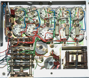
Above: Note that previously L15 and L21 were of the same style of inductor as used in the 1MHz LP filter ... a style which unfortunately suffers from physical deterioration as a result of age where the coil former literally disintegrates. The small inductor on top of L15 in the RA237 is L38.
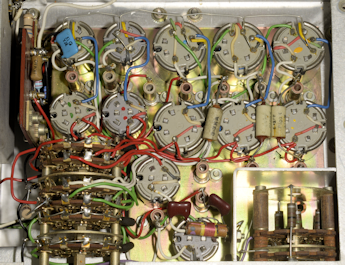
Above: Note that L32 now uses the more robust style of construction. Also note that the Mixer board in the RA137 is actually pre-drilled to take the crystal and trimmer as fitted in the RA237.
Above: And a similar standardisation of inductor style applies to the Harmonic Generator assembly.
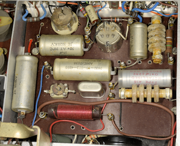
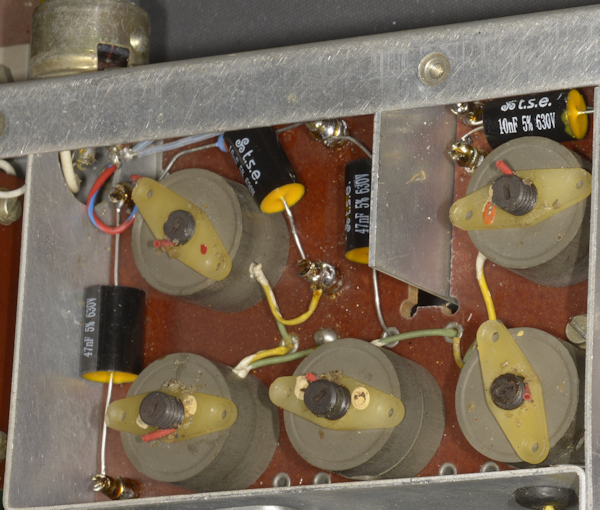
Unfortunately, the 1MHz Low Pass filter between the RF Amplifier and the Balanced Mixer still employs the nasty brittle coil formers and L25 (bottom right in the photograph below) had a shattered former which I had to replace. Those of us who started out modifying ex-PMR kit in the 1970s will recognise these as the same formers and shielded cores that Pye used in the 10.7MHz board in the Cambridge and Vanguard mobile radios, and I got to thinking that such boards could be salvaged for spare formers. But then it struck me that since these too date from the 1960s, so too would the formers be well down the road to disintegration.
I remembered that there is a 'safety' modification with the 1MHz LP Filter but initially couldn't remember where it was listed. It turns out to be an addendum in the RA137 manual that I have. Curiously, this mod wasn't present in the RA237 in front of me, yet at least one of the mods listed (fitting L38) had been done. In short, the mod in question protects the inductors in the LP filter from burning out if any of the ceramic capacitors were to go short-circuit. Initially, the input to the filter was dc-coupled to the anode of the RF amplifier stage. Since this is a Low Pass filter, all the inductors are in series, and should C36, C38, C43 or C44 go short-circuit, the 150V present at the anode of V1 would appear across all the inductors 'to the left' of the capacitor that had failed ... with the result, smoke would prevail!
The mod involves inserting a 10nF capacitor between V1 anode (pin 5) and the junction of L22/C32 ... essentially replacing the red and blue wire in the photograph above with the 10nF capacitor. You also have to re-position R17 (4K7) by disconnecting the end which goes to L22 and re-connecting it to V1 pin 5 (anode).
The above photograph shows the added 10nF capacitor. Unfortunately R17 is not visible and the new R18 (33K) is only just visible under C68 (the new capacitor). The RA237, like the RA137 and the RA37 is a tad awkward to work on due to the design of the chassis which is formed from a U-shaped aluminium channel folded into a rectangle.
The two photographs above show the underside of the Balanced Mixer board as received and after refurbishment, whilst the photograph below shows the upper-side of the mixer board after refurb. A pre-refurb photograph can be seen earlier in this article.
 That more or less sums up the work carried out on the RA237B. Apart from replacing all the carbon resistors (with the exception of those in the antenna attenuator) and tubular paper/electrolytic capacitors, only one part needed replacing; the damaged coil former in the 1MHz LP filter. However, the mylar sheet on which the preselector scales are marked had obviously come off the drum and had been unceremoniously sellotaped back in place ... not longitudedly, as one might expect, but literally spirally, around the drum. Once removed and cleaned, I re-fitted the sheet back onto the drum using thin double-sided tape at the start and finish. As with the RA137 and RA37, I have not replaced the resistors in the attenuator because it is impossible to remove this part, and thus gain access to the resistors, without completely dismantling the entire chassis!
Alignment was a breeze. The Harmonic Generator is simply adjusted for maximum output, and the pre-selector ranges were set using the same procedure as given in the manual. Since my RF signal generators don't go low enough in frequency, I used my HP3325A Function Generator for this purpose. Checking the 1MHz LP filter was achieved using my Rigol Spectrum Analyzer with Tracking Generator. To compensate for the fact that the filter is NOT 50-ohms I simply inserted a 1K resistor at each end.
Balancing the mixer was carried out after a warm-up period of 30 minutes. From the manual it is clear that the unit is primarily intended for Wideband operation, with the tuneable preselector ranges being 'inserted' when interference from strong 'in-band' signals presented itself.
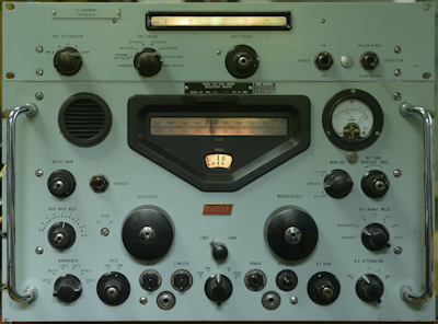
Left: The RA117 with the RA237B sitting on top, tuned to BBC Radio 4 on 198KHz.
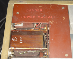
Right: Who else thinks it odd to refer to Mains Voltage as Power Voltage?
- The Racal RA137A
- The Racal RA37A
- LF Converter Type RA237B
September 2024
Glance at the schematic for the RA237B and you could be forgiven for thinking that it is identical to the RA137 ... except if you dwell a little longer you will notice a nominally 2MHz crystal across the input to the Cathode follower on the output. Functionally, that is the only difference. The crystal acts as a rather crude notch-filter at 2MHz, to compensate for the fact that the RA117 (for which the RA237 is designed to interface with) does not have the same IF pass-band filtering as the RA17 etc. The notch is there to reduce the amount of 2MHz leak-through from the Harmonic Generator (in the RA237) at the RF output. The crystal itself is 1999.30KHz, which sounds a bit odd, but I suspect this 'offset' is to compensate for the 10pF pulling-capacitor which is in series with it.
Other deviations from the RA137 include the use of North American valves, which is to be expected since that is in line with the RA117. The RF amplifier (V1, 6BA6) is the same, as is the voltage stabiliser (V5, OA2). The S6F33s in the Balanced mixer are changed to 6AS6s, and the Cathode Follower in the output and the Harmonic Generator are both now 6AU6s. Note: Although the 6AS6 is electrically identical to the S6F33 it is not a direct replacement since grids 2 and 3 are swapped.
Elsewhere there are a few passive component changes. C29 and C49 are now both 25uF (22uF fitted), and C38 is now 4uF (4u7F fitted). There are also a few minor resistance changes in line with the different valves used. The RA237 schematic shows no 180R resistors in series with the Control Grids on the 6AS6s, however they were present in this case. There has also been a change to some of the variable inductors see below ...
RA137 Preselector
RA237 Preselector
Above: Note that previously L15 and L21 were of the same style of inductor as used in the 1MHz LP filter ... a style which unfortunately suffers from physical deterioration as a result of age where the coil former literally disintegrates. The small inductor on top of L15 in the RA237 is L38.
RA137 Mixer
RA237 Mixer (before refurb)
Above: Note that L32 now uses the more robust style of construction. Also note that the Mixer board in the RA137 is actually pre-drilled to take the crystal and trimmer as fitted in the RA237.
RA137 Harmonic Generator
RA237 Harmonic Generator
Above: And a similar standardisation of inductor style applies to the Harmonic Generator assembly.
Unfortunately, the 1MHz Low Pass filter between the RF Amplifier and the Balanced Mixer still employs the nasty brittle coil formers and L25 (bottom right in the photograph below) had a shattered former which I had to replace. Those of us who started out modifying ex-PMR kit in the 1970s will recognise these as the same formers and shielded cores that Pye used in the 10.7MHz board in the Cambridge and Vanguard mobile radios, and I got to thinking that such boards could be salvaged for spare formers. But then it struck me that since these too date from the 1960s, so too would the formers be well down the road to disintegration.
1MHz Low-Pass Filter
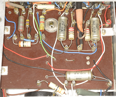
I remembered that there is a 'safety' modification with the 1MHz LP Filter but initially couldn't remember where it was listed. It turns out to be an addendum in the RA137 manual that I have. Curiously, this mod wasn't present in the RA237 in front of me, yet at least one of the mods listed (fitting L38) had been done. In short, the mod in question protects the inductors in the LP filter from burning out if any of the ceramic capacitors were to go short-circuit. Initially, the input to the filter was dc-coupled to the anode of the RF amplifier stage. Since this is a Low Pass filter, all the inductors are in series, and should C36, C38, C43 or C44 go short-circuit, the 150V present at the anode of V1 would appear across all the inductors 'to the left' of the capacitor that had failed ... with the result, smoke would prevail!
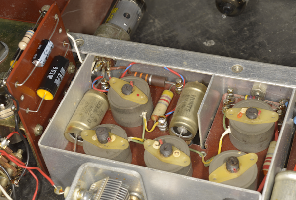
The mod involves inserting a 10nF capacitor between V1 anode (pin 5) and the junction of L22/C32 ... essentially replacing the red and blue wire in the photograph above with the 10nF capacitor. You also have to re-position R17 (4K7) by disconnecting the end which goes to L22 and re-connecting it to V1 pin 5 (anode).
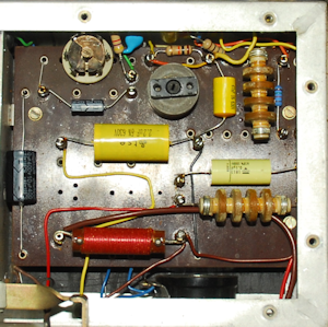
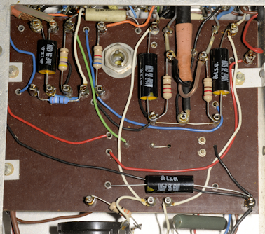
1MHz Low-Pass Filter, modified and refurbished
The above photograph shows the added 10nF capacitor. Unfortunately R17 is not visible and the new R18 (33K) is only just visible under C68 (the new capacitor). The RA237, like the RA137 and the RA37 is a tad awkward to work on due to the design of the chassis which is formed from a U-shaped aluminium channel folded into a rectangle.
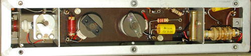
RA237B Balanced Mixer before refurbishment
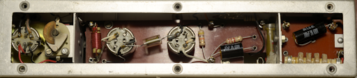
RA237B Balanced Mixer after refurbishment
The two photographs above show the underside of the Balanced Mixer board as received and after refurbishment, whilst the photograph below shows the upper-side of the mixer board after refurb. A pre-refurb photograph can be seen earlier in this article.
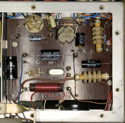
Upper-side of mixer board after refurb.
Alignment was a breeze. The Harmonic Generator is simply adjusted for maximum output, and the pre-selector ranges were set using the same procedure as given in the manual. Since my RF signal generators don't go low enough in frequency, I used my HP3325A Function Generator for this purpose. Checking the 1MHz LP filter was achieved using my Rigol Spectrum Analyzer with Tracking Generator. To compensate for the fact that the filter is NOT 50-ohms I simply inserted a 1K resistor at each end.
Balancing the mixer was carried out after a warm-up period of 30 minutes. From the manual it is clear that the unit is primarily intended for Wideband operation, with the tuneable preselector ranges being 'inserted' when interference from strong 'in-band' signals presented itself.
Finished!
Left: The RA117 with the RA237B sitting on top, tuned to BBC Radio 4 on 198KHz.
Right: Who else thinks it odd to refer to Mains Voltage as Power Voltage?
Odd choice of words.