Racal RA66B Panoramic Adaptor
23 minute read
August 2024
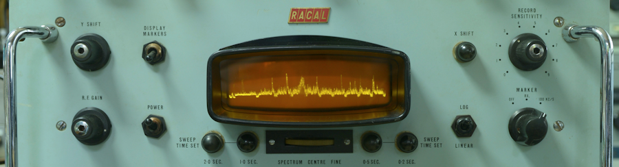
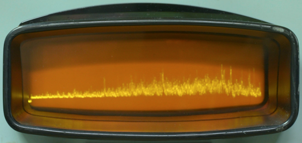
When you think about it, with the exception of an SSB Adaptor, a Panoramic Adaptor is actually an obvious addition to a receiver installation ... and who isn't mesmerised by the soft amber trace?
As I said, this isn't mine, this one belongs to a valued client. It arrived with it's partnered MK2 RA17, complete with MA251 adaptor, and looked nothing like the photograph above.
Oops!.
The outside of the left-hand side panel was awash with mineral-oil residue. Removing the bottom cover revealed that the EHT transformer had literally sprayed its oil content out over the bottom panel. The 100K resistor in series with the the EHT winding was 'cooked' but still measuring 100K. However the special High Voltage base for V29 (1X2A) was in a very bad way. In fact as the photographs below show, the valve base had actually melted such that it had enveloped the valve to the extent that removing the valve was a serious challenge.
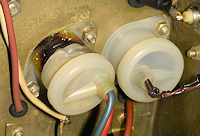
Melted valve base.
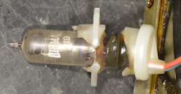
Valve and base are melded.
Needless to say, this was a bit of a set-back. However, all was not lost. My client is someone with many 'connections', and knew someone who would be able to repair the transformer. Whilst the transformer was sent off to be repaired and the remains of the valve base were used as a pattern for a replacement (a McMurdo replacement was not an option), I set about cleaning the chassis and chasing down the cause of the disaster.
 A truly filthy chassis!
I get the impression that this RA66 had at one time been stored on its side, judging by the pooling of mineral oil. Then at some time it had spent time horizontal ... hence the obvious dark oily patch in the centre of the chassis (above).
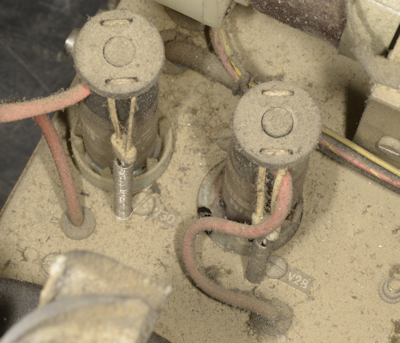
Wrong label.
Right: Here's an obvious manufacturing error. These are the two EHT rectifiers, V29 and V30, before I removed the melted socket. Only; V29 is labelled V28. V28 is one of the VR150/30 voltage stabilisers.
Also, despite the fact that the heaters in both rectifiers were intact, both failed the diode-test on my valve tester.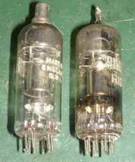
The schematic in the manual shows V29 and V30 as type 1X2A, typically used in televisions around that time (early 1960s). Type 1X2B (or R19) is given as an alternative, and indeed the Items List gives the valve type as 1X2B, which apparently offers a higher average anode current capability (500uA versus 175uA)... not that such a thing is important here ... although something had obviously been drawing a whole lot of current.
There are four very expensive Visconol Capacitors in the RA66. These are each 0.1uF/5KV rating. I checked each one in turn for leakage, but in the absence of an insulation tester, I was limited to checking for resistance significantly less than 20M-ohms. All four capacitors checked out OK, although C109 (Fly-Back suppression) was covered in mineral oil of a finer type than that ejected by the transformer. I passed this information on to my client who immediately ordered a 'suitable' replacement. The replacement turned out to be 100nF/4KV rating, but in the Fly-Back circuit, that would suffice.
As I waited for the transformer and custom-made replacement valve base to arrive, I set about cleaning-up the chassis. This turned out better than expected. The solidified mineral oil was easily scraped off with a large wood-chisel and Isopropyl alcohol did the rest. I soon had the top-side of the chassis looking very smart. I also started on the task of replacing all the old carbon-composite resistors and at-risk tubular paper capacitors, the bulk of which appeared to be 10nF. Because of the RA66's complex power-supply, there were, as well as the big Visconol capacitors, three twin smoothing packs and at least another three or four electrolytics. Below is a photograph of the underside of the RA66 nearing completion.
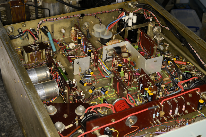 Component replacement nearing completion. Internal covers removed.
There is an issue, a problem with the manual for the RA66. There are only two copies available on-line. Both are identical in content, but they have different file-names. Although the text is generally very readable, the schematic is not so good ... in some cases 3s and 5s are indistinguishable, and there are inconsistencies between the schematic and the Items List. Both copies have an addendum relating to the changes introduced in the RA66B. However even these are incorrect, and the amended schematic is of shocking quality.
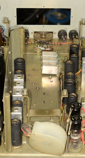
The photograph on the left shows the centre of the chassis with the tube removed. The three horizontally mounted cans are the 3.2MHz low-pass filter on the input to the Local Oscillator Input. I can't help thinking that this was an after-thought. Between the filter and the 'Spectrum Centre Fine' control is a cluster of resistors on a tag-board. These are key to what makes the difference between an RA66 and an RA66B. The latter has four sweep rates whilst the former only has two, 0.25 sec and 2.5 sec.
As said, the added features of the RA66B are described in the addendum at the end of the manual, however, to summarise the difference between an RA66 and an RA66B:
The Sweep Generator circuit is completely different.
The RA66B offers four sweep-rates of 0.2 sec, 0.5 sec, 1 sec and 2 sec.
The RA66B provides a buffered signal (video) output via V34 (6AU6).
The RA66B provides for an externally generated Sweep Trigger input.
In the RA66B, the circuitry around V24 (12AT7) has been modified to provide a CAL o/p.
The RA66B was most likely the result of the RA166 Panoramic Recording Receiver (Panfax) which facilitated the recording of the spectrum under examination in hard-copy form.
The RA66B employs a completely different design of Sweep Oscillator. The original circuit in the RA66 is based around a Miller Integrator design. However the new design employed in the RA66B is based on a design known as a Phantastron (Yes, I kid you, not.), which is based on the Miller Integrator. Without going into how this circuit works in great detail, the idea is that the Phantastron makes use of the valve's Suppressor Grid to speed up the Fly-Back part of the Saw-Tooth waveform by making it negative with respect to the cathode. The name Phantastron was likely conned by someone who was very impressed with the circuit's performance ... what a wonderful name!
In providing four selectable Sweep Rates, SC1F is now 2-pole 8-way and we have four preset controls on the front panel. This is where reading, or trying to read the schematic becomes a problem. The four front panel Presets look like RV14, RV16, RV18 and RV19. The items list stops at RV13 so these designations may be correct. In series with each of these potentiometers we have a fixed value resistor. These are the cluster of resistors previously mentioned above, and shown in clearer detail below.
From the modified schematic in the addendum of the manual, these resistors look like R165 (1M), R170 (1M5), R172 (3M3) and R176 (10M). However I found that whereas the four potentiometers were as per the schematic, the values of two of the fixed resistors were different. I found that R165 was 820K and R176 was 8M2.
The repaired and re-filled EHT transformer arrived along with a pair of brand new (Old Stock) 1X2A rectifier valves and a custom-made high-voltage B9A valve socket. By now I had almost completed replacing all the carbon resistors and tubular paper capacitors. This task included re-stuffing three twin-33uF/450V smoothing packs. I had borrowed a X1000 HV probe for checking the EHT PSU which by way of a voltage doubler should deliver nominally 4.4KV, and I would be powering the RA66 from a variac, bringing the mains on slowly.
I wasn't going to rush things, afterall, a belt from a 4.5KV power supply can seriously ruin your day, although I did fit the repaired transformer and new valve socket. Once all the Rs and Cs in the RA66 were replaced or refurbished, I cleared the bench, making sure nothing was likely to accidentally fall into the RA66. I connected the RA66 to the output of my variac and connected the HV probe to the junction of C119 and R148 and slowly wound up the mains voltage. At bout 170V input, I spotted a wisp of smoke coming from R97 (100K). I also noted that the HT appeared a bit low at 2KV. A quick glance at the two 1X2A rectifiers revealed that only one of them appeared to be working ... only V29 was glowing.
However, I very quickly realised that what I was seeing was NOT heater-glow, but the Anode of V29 glowing orange! WOOPS! I quickly cranked the variac back to 0%. We have a problem, I thought. The HV probe confirmed that the voltage at C119 was 0V, so I measured the resistance across it ... 450 ohms! That's not right! This was very likely the cause of the problem and also, very likely the same fault that had precipitated the melt-down of V29 some time in the past. This also had me thinking that C109, which I had previously replaced, might actually be OK. It is very likely that the fault (breakdown) in C119 was only present at high voltage, and that winding the mains voltage up via the variac prevented a catastrophic and expensive failure occurring. Good investment, that variac.
So, out came C119, to be replaced with the original C109. Back to the variac. Slowly wind up the voltage whilst keeping an eye on the rectifiers, and the HT ... which now increases past 2KV, past 3KV and finally settles on 4.4KV. Not only that, I now have a very reassuring trace on the CRT. We have a working RA66 ... almost. Three out of the four sweep-rates were functioning. However the slowest rate (2Sec) would only work in the triggered mode. This fault turned out to be nothing more than a failed, open-circuit Germanium diode, MR3, OA81. I replaced it with a 1N4149 which resolved the problem. I then replaced MR2, also an OA81 with a 1N4149 for good measure ... germanium devices are known to be less robust than silicon types.
But let's go back to the EHT Power Supply ...
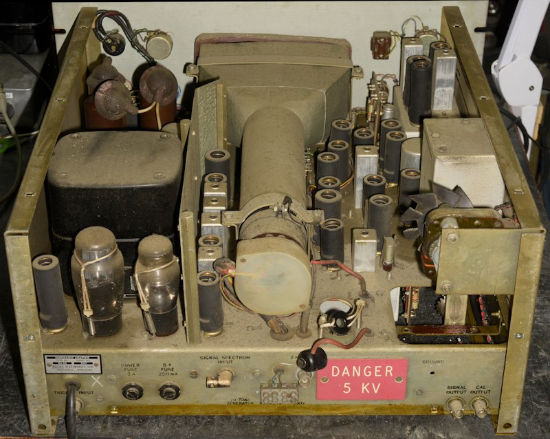
When you first look at the schematic for the RA66, it isn't immediately obvious how the 4.4KV is achieved. First of all, the RA66 has two mains transformers, T1 and T2. The latter provides the conventional HT lines of +350V, +300V, +260V, +150V and -110V ... all via two full-wave valve rectifiers (although one is configured as half-wave) and no less than three 150V stabilising valves (VR150/30). T1 provides for the CRT and curiously has a primary winding which is wound for 110V, as is the little fan which really only keeps the air under the lid moving. Both of which are in parallel across one half of T2's primary. T2 also caters for all the valve heaters with the exception of the CRT and V29.
Also, despite the fact that the heaters in both rectifiers were intact, both failed the diode-test on my valve tester.
Two duff rectifiers.
The schematic in the manual shows V29 and V30 as type 1X2A, typically used in televisions around that time (early 1960s). Type 1X2B (or R19) is given as an alternative, and indeed the Items List gives the valve type as 1X2B, which apparently offers a higher average anode current capability (500uA versus 175uA)... not that such a thing is important here ... although something had obviously been drawing a whole lot of current.
There are four very expensive Visconol Capacitors in the RA66. These are each 0.1uF/5KV rating. I checked each one in turn for leakage, but in the absence of an insulation tester, I was limited to checking for resistance significantly less than 20M-ohms. All four capacitors checked out OK, although C109 (Fly-Back suppression) was covered in mineral oil of a finer type than that ejected by the transformer. I passed this information on to my client who immediately ordered a 'suitable' replacement. The replacement turned out to be 100nF/4KV rating, but in the Fly-Back circuit, that would suffice.
As I waited for the transformer and custom-made replacement valve base to arrive, I set about cleaning-up the chassis. This turned out better than expected. The solidified mineral oil was easily scraped off with a large wood-chisel and Isopropyl alcohol did the rest. I soon had the top-side of the chassis looking very smart. I also started on the task of replacing all the old carbon-composite resistors and at-risk tubular paper capacitors, the bulk of which appeared to be 10nF. Because of the RA66's complex power-supply, there were, as well as the big Visconol capacitors, three twin smoothing packs and at least another three or four electrolytics. Below is a photograph of the underside of the RA66 nearing completion.
Component replacement nearing completion. Internal covers removed.
Under the tube.
There is an issue, a problem with the manual for the RA66. There are only two copies available on-line. Both are identical in content, but they have different file-names. Although the text is generally very readable, the schematic is not so good ... in some cases 3s and 5s are indistinguishable, and there are inconsistencies between the schematic and the Items List. Both copies have an addendum relating to the changes introduced in the RA66B. However even these are incorrect, and the amended schematic is of shocking quality.
The photograph on the left shows the centre of the chassis with the tube removed. The three horizontally mounted cans are the 3.2MHz low-pass filter on the input to the Local Oscillator Input. I can't help thinking that this was an after-thought. Between the filter and the 'Spectrum Centre Fine' control is a cluster of resistors on a tag-board. These are key to what makes the difference between an RA66 and an RA66B. The latter has four sweep rates whilst the former only has two, 0.25 sec and 2.5 sec.
As said, the added features of the RA66B are described in the addendum at the end of the manual, however, to summarise the difference between an RA66 and an RA66B:
The Sweep Generator circuit is completely different.
The RA66B offers four sweep-rates of 0.2 sec, 0.5 sec, 1 sec and 2 sec.
The RA66B provides a buffered signal (video) output via V34 (6AU6).
The RA66B provides for an externally generated Sweep Trigger input.
In the RA66B, the circuitry around V24 (12AT7) has been modified to provide a CAL o/p.
The RA66B was most likely the result of the RA166 Panoramic Recording Receiver (Panfax) which facilitated the recording of the spectrum under examination in hard-copy form.
The RA66B employs a completely different design of Sweep Oscillator. The original circuit in the RA66 is based around a Miller Integrator design. However the new design employed in the RA66B is based on a design known as a Phantastron (Yes, I kid you, not.), which is based on the Miller Integrator. Without going into how this circuit works in great detail, the idea is that the Phantastron makes use of the valve's Suppressor Grid to speed up the Fly-Back part of the Saw-Tooth waveform by making it negative with respect to the cathode. The name Phantastron was likely conned by someone who was very impressed with the circuit's performance ... what a wonderful name!
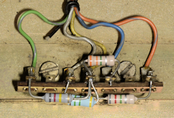
In providing four selectable Sweep Rates, SC1F is now 2-pole 8-way and we have four preset controls on the front panel. This is where reading, or trying to read the schematic becomes a problem. The four front panel Presets look like RV14, RV16, RV18 and RV19. The items list stops at RV13 so these designations may be correct. In series with each of these potentiometers we have a fixed value resistor. These are the cluster of resistors previously mentioned above, and shown in clearer detail below.
Resistor cluster.
From the modified schematic in the addendum of the manual, these resistors look like R165 (1M), R170 (1M5), R172 (3M3) and R176 (10M). However I found that whereas the four potentiometers were as per the schematic, the values of two of the fixed resistors were different. I found that R165 was 820K and R176 was 8M2.
The repaired and re-filled EHT transformer arrived along with a pair of brand new (Old Stock) 1X2A rectifier valves and a custom-made high-voltage B9A valve socket. By now I had almost completed replacing all the carbon resistors and tubular paper capacitors. This task included re-stuffing three twin-33uF/450V smoothing packs. I had borrowed a X1000 HV probe for checking the EHT PSU which by way of a voltage doubler should deliver nominally 4.4KV, and I would be powering the RA66 from a variac, bringing the mains on slowly.
I wasn't going to rush things, afterall, a belt from a 4.5KV power supply can seriously ruin your day, although I did fit the repaired transformer and new valve socket. Once all the Rs and Cs in the RA66 were replaced or refurbished, I cleared the bench, making sure nothing was likely to accidentally fall into the RA66. I connected the RA66 to the output of my variac and connected the HV probe to the junction of C119 and R148 and slowly wound up the mains voltage. At bout 170V input, I spotted a wisp of smoke coming from R97 (100K). I also noted that the HT appeared a bit low at 2KV. A quick glance at the two 1X2A rectifiers revealed that only one of them appeared to be working ... only V29 was glowing.
However, I very quickly realised that what I was seeing was NOT heater-glow, but the Anode of V29 glowing orange! WOOPS! I quickly cranked the variac back to 0%. We have a problem, I thought. The HV probe confirmed that the voltage at C119 was 0V, so I measured the resistance across it ... 450 ohms! That's not right! This was very likely the cause of the problem and also, very likely the same fault that had precipitated the melt-down of V29 some time in the past. This also had me thinking that C109, which I had previously replaced, might actually be OK. It is very likely that the fault (breakdown) in C119 was only present at high voltage, and that winding the mains voltage up via the variac prevented a catastrophic and expensive failure occurring. Good investment, that variac.
So, out came C119, to be replaced with the original C109. Back to the variac. Slowly wind up the voltage whilst keeping an eye on the rectifiers, and the HT ... which now increases past 2KV, past 3KV and finally settles on 4.4KV. Not only that, I now have a very reassuring trace on the CRT. We have a working RA66 ... almost. Three out of the four sweep-rates were functioning. However the slowest rate (2Sec) would only work in the triggered mode. This fault turned out to be nothing more than a failed, open-circuit Germanium diode, MR3, OA81. I replaced it with a 1N4149 which resolved the problem. I then replaced MR2, also an OA81 with a 1N4149 for good measure ... germanium devices are known to be less robust than silicon types.
But let's go back to the EHT Power Supply ...
When you first look at the schematic for the RA66, it isn't immediately obvious how the 4.4KV is achieved. First of all, the RA66 has two mains transformers, T1 and T2. The latter provides the conventional HT lines of +350V, +300V, +260V, +150V and -110V ... all via two full-wave valve rectifiers (although one is configured as half-wave) and no less than three 150V stabilising valves (VR150/30). T1 provides for the CRT and curiously has a primary winding which is wound for 110V, as is the little fan which really only keeps the air under the lid moving. Both of which are in parallel across one half of T2's primary. T2 also caters for all the valve heaters with the exception of the CRT and V29.
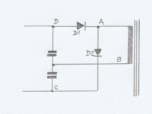
Classic Voltage Doubler circuit.
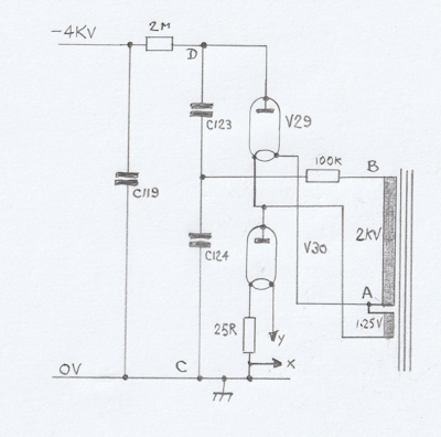
Voltage doubler in the RA66.
To get my head around just how the voltage doubler worked, I drew the two schematics above. A search on the internet for voltage doublers will return various incarnations of the image above left. I have drawn it as a doubler which generates a voltage where D is negative with respect to C whilst A and B are the AC source. I have also drawn it with the AC source on the right, as in the RA66 schematic.
Now turning our attention to the voltage doubler in the RA66; what isn't immediately obvious is the role V30 plays in the doubler. As previously mentioned, whereas T1 provides the 1.25V at 200mA heater supply for V29, V30 gets its heater current from the bulk 6.3V heater winding on T2 via a 25-ohm resistor. The RA66 schematic shows V30 heater going to points 'x' and 'y' ... look at the 6.3V 4A winding on T2 and you will see 'x' and 'y', with 'x' connected to chassis ... and so, it now makes sense. I then drew out the RA66 doubler circuit so as to mimic the basic doubler, with points A, B, C and D.
Wiring V30 in this manner is actually very clever, or at least sensible. Since the cathodes in the two rectifiers are directly heated (the heater is the cathode), it would not be possible to run both heaters from the same winding as V30 would be shorted out. The fact that V30 is required to be connected to chassis, taking the heater current from the bulk heater supply is the obvious choice since one side of that winding is connected to chassis. All that is required is a 25-ohm resistor to drop the heater voltage at the rectifier to nominally 1.25V.
Is there a reason why this doubler generates a voltage that is negative with respect to chassis? Its all a question of potential difference. It is a requirement that the potential applied to the three anodes in the CRT is positive with respect to the cathode, which it is ... because the output of the voltage doubler is more or less connected to the CRT cathode ... and the fact that the CRT anodes are connected to +150V means that the potential difference is a further 150V above the cathode.
Is the RA66 as complicated as the schematic looks? Not really ...
The way to tackle understanding the RA66 is to metaphorically break it into a series of components. With respect to the schematic, the top 'row' is essentially a dual conversion broad-band receiver with an input covering 2MHz to 3MHz. The first IF is 1.5MHz and a second IF is 100KHz. Selectivity is provided by a 100KHz L-C filter identical to that found in an RA17. The first Local Oscillator (V20, 6AS6) sweeps from 3.5MHz to 4.5MHz and is synchronised to the Saw Tooth Sweep Generator previously described. Unfortunately, the physical layout of the RA66 does not make it easy to present photographs of the individual parts as given in the block diagram in the manual. Thus, I have created the photograph below to help identify the individual parts of the RA66.
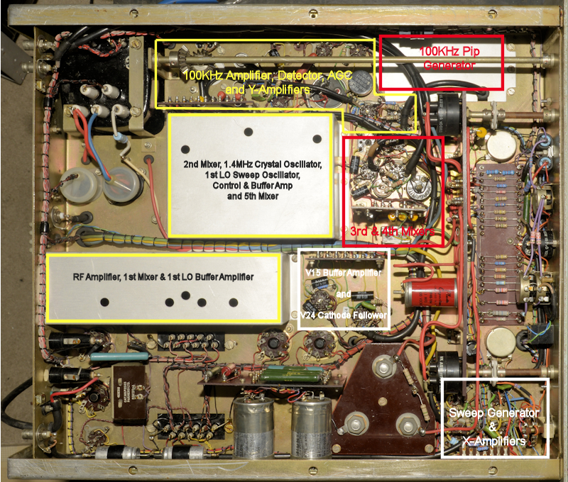 If it isn't identified above, it is either PSU-related or CRT-Control-related.
The RA66 is connected to its host receiver via two coax cables. These are the 'Signal Spectrum Input' which is the output of the RA17's second mixer stage, spanning 2MHz - 3MHz. The other is the '2nd VFO Input', which is a sample of the RA17's second Local Oscillator (2.1MHz - 3.1MHz). You could use an RA17L as the host receiver but modifications are required to disconnect the AGC from the receiver's RF amplifier stage. The reason for this is quite simple ... It is vitally important that the gain of the receiver stages before the third mixer are not influenced by AGC, as this could result in a misleading compressed-amplitude display where strong signals were concerned. Details on this modification are given in the manual.
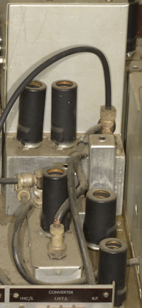
MA251 Buffer Stage.
It is also important that the host receiver be fitted with an MA251 Buffer Stage. This is not, as one might think, a buffer stage between the receiver and the RA66. It is in fact inserted into the receiver signal path such that there is no signal degradation and receiver performance is not affected. The photograph on the left shows the MA251 in a somewhat grubby state prior to refurbishment. The input to the MA251 is very similar to the unit that it replaces. The shorter of the two 'cans' contains a series-resonant circuit, identical to L52 in the RA17, which is designed to eliminate leak-through of any 37.5MHz signal. The taller of the two 'cans' contains two parallel-tuned traps, L51A and L51B, who's purpose initially appears to be the removal of unwanted signals at 2MHz and 4MHz. I even have a circuit diagram with hand-written notes suggesting that L51A is tuned to 3MHz and L51B to 2MHz. But things are not what they appear to be.
What you have to bear in mind is that at its widest, the display on the RA66 mimics the KHz scale on the host receiver; i.e. when the receiver is tuned to 3MHz, the extreme right of the trace is 3MHz and the left edge is 4MHz. Thus when the procedure in the manual tells you to set the receiver to 3MHz and adjust L51A to reduce the spurious signal present at the first marker (extreme left-hand), you are eliminating a 'spur' at 4MHz. Likewise, when the receiver is set to 2MHz and you are instructed to adjust L51B to reduce the spurious signal at the extreme right of the display, you are eliminating a 'spur' at 2MHz.
So, does that mean that the L51A and L51B are tuned to 4MHz and 2MHz respectively? Nope!
When I came to perform these adjustments, my initial problem was that I wasn't seeing any significant 'spurs' at the ends of the trace. So I looked at the spectrum of the input signal on one of my spectrum analysers and found that when the receiver MHz dial was set to 2, there was a signal at 5MHz, and when the dial was set to 3, there was a signal at 6MHz.
Here's what's going on ...
Remember that at this point in the receiver, the tuning is effectively inverted: 3MHz equates to 2MHz and vice versa. When The MHz dial is at 3, there is an unwanted 6MHz signal present. The left-most edge of the 1MHz-wide display is thus 4MHz and at this point in the receiver, this equates to 2MHz. Subtracting 2 from 6 we get 4. Thus L51A removes what looks like a spur at 4MHz but is in fact eliminating the 6MHz signal.
Then, when the MHz dial is set to 2, there is an unwanted 5MHz signal present. The right-most edge of the 1MHz-wide display is 2MHz which equates to 3MHz. Subtracting 3 from 5 we get 2. Thus L51B removes what looks like a spur at 2MHz but is in fact eliminating the 5MHz signal.
Thus, L51A is tuned to 6MHz and L51B is tuned to 5MHz ... and this means that some of the information in my earlier article on the MA251 is incorrect, which I will amend in due course.
As mentioned, a sample of the host receiver's 2nd VFO is connected to the RA66 and fed to the 4th mixer (V13, 6AS6). This connection is not functionally vital as it only serves to generate a calibration mark on the trace in the form of a negative going 'pip' which enables the operator to identify the frequency of a signal by adjusting the receiver KHz dial to position the tuning 'pip' at the point of interest on the trace and then reading the exact frequency off the KHz scale on the receiver.
Initially there was a problem with this feature in that the tuning 'pip disappeared if the KHz was less than 150KHz (2nd VFO greater than 3.05MHz). This was caused by a misalignment of the 3.2MHz LP filter hiding under the CRT. Obviously I had to remove the CRT in order to make the necessary adjustment. The drop-off above 3MHz was noticeably steep and it was relatively easy to 'nudge' the knee slightly HF. It was then a case of re-fitting the CRT and seeing if the tuning marker was visible over the entire 1000KHz band ... which, thankfully it was.
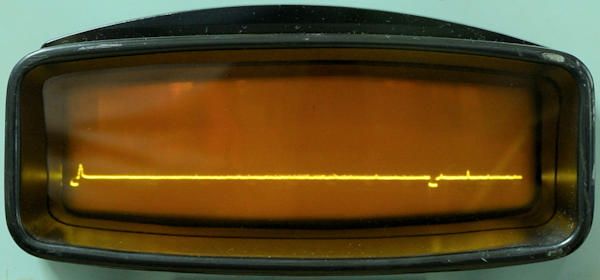 Tuning Marker.
As well as the tuning marker, the RA66 also provides marker 'pips' at 100KHz spacing. These are generated by the Pip Generator which generates a comb of signals corresponding to the 35th to 45th harmonics of the 100KHz fundamental. Obviously this is more sophisticated than the harmonic generator in the RA17, and there's a reason for this. The RA66 has mixers operating at 100KHz, 1.4MHz, and 1.5MHz. It is therefore necessary to avoid generating harmonics at these frequencies. Thus, the anode circuit of V17B (12AT7) forms a band-pass filter covering approximately 1MHz centred on 4MHz. The output of which is then amplified by V18 (6AU6) where further filtering ensures that only the eleven harmonics between 3.5MHz and 4.5MHz are passed to the 5th mixer (V14, 6AS6). The combined outputs of the 4th and 5th mixers are then filtered before being amplified by V15 (12AT7) to the point that large constant amplitude negative going pulses are produced. V24A (12AT7), which is configured as a monostable, then generates the actual marker pulses. The output of which is capacitively coupled to the Y1 plate of the CRT, causing a momentary dip in the trace. I think that makes sense.
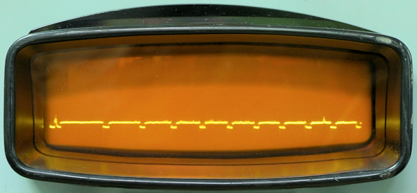 Eleven 100KHz Markers.
As is obvious from the image above, the output from the sweep generator isn't linear. Perfectionists might instantly identify this is a problem. A good reason why the slight non-linearity of the trace need not be a problem is that since the sweep-width is infinitely variable by design ... which is why there isn't a graticule inscribed on the amber filter, the calibration is taken care of by the markers. Note also the the filter is at an angle ... the top of the filter is further away from the CRT. I believe this is to avoid distracting reflections.
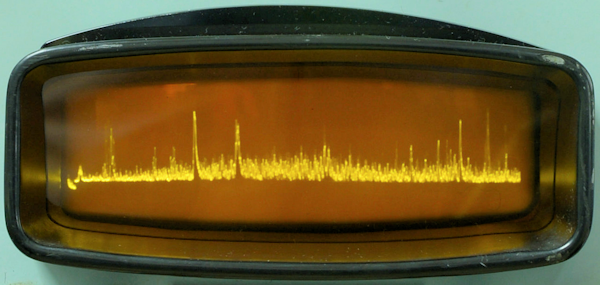 Busy 20m spectrum with markers switched off.
 A sweep of 7.0MHz to 7.1MHz
The image above shows a sweep of the 40m band between 7.0MHz and 7.1MHz. Remember, 7.0MHz is the extreme right edge of the trace. The tuning marker can be seen at 7.128MHz. Interestingly, the trace also reveals the frequency response of my Inverted-V.
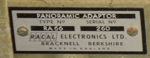
Serial Plate.
Throughout this article I have referred to this Panoramic Adapter as an RA66, simply because that's what it says on the serial plate. However, this is very definitely an RA66B, which was developed for the RA166 Panoramic Recording Receiver.
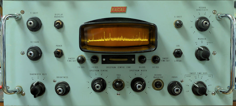 Repaired and refurbished RA66B
This was quite an epic repair-job. At the end of the day I had replaced both 1X2A EHT rectifiers, one high-voltage valve socket, one High-Voltage capacitor, ALL ten 6AU6s which were exhibiting poor heater-cathode insulation of varying degrees, two 6BA6s, three 12AT7s, and one each 6BE6 and 6AS6. The day after I declared it fully functional, I switched it on and noticed a bright flash from inside the HT fuse-holder (the RA66 was on its side). Interesting, I thought. Sure enough, the fuse was blown ... so I replaced it (as if that was going to fix it ... right!). This time this fuse and the 3A fuse in the plug blew. OK ... replacing the fuse again isn't going to fix the problem. I decided to check the big 5V4 rectifier. Yup! faulty! On the VCM-163, the heater glowed but it failed the diode/rectifier test. I fitted a GZ37 as a temporary fix and everything was 'sweetness and light' again. I would have left it at that, but the GZ37 is so big that it was in danger of touching the top cover. So I bought a brand-new 5V4GT ... so add that to the list of replaced valves.