MKII 9cm Transverter
7 minute read
Woops!
February 2007
Its now February 2007, traditionally the time of year for those of us who construct our own equipment, to do the constructing ... Hmm?
Lets just say that the Ionica enclosure for my mast-mounted 9cm transverter failed the water ingress test ... twice! But lets be fair about it, on each occasion, the rain had been accompanied by 50-60 mph winds ... and I was partly to blame for the first incident by failing to seal off a couple of unused holes in the PA heat-sink. Prior to the second incident, Nick, GM4OGI and myself had been having great fun on 3.4GHz during a heavy sleet shower ... the stronger the wind the greater the Doppler shift ... the less intelligible the signal. The weather really was atrocious. But something was definitely wrong. After a while, maybe 30 minutes, my Local Oscillator began to make dramatic shifts during transmit, then reset itself during the Receive period to the extent that Nick and I ended up chasing each other all over the band. I was monitoring my LO on my IC706, so I knew the fault rested with me. After several days of torrential sideways rain, it was clear that the transverter was no longer generating RF, so during a temporary lull in the weather, I ventured up onto the roof and drilled a hole in the box. I estimate about 100ml of water poured out. I retested the box after allowing it time to dry but it still wouldn’t work.
Lets just say that the Ionica enclosure for my mast-mounted 9cm transverter failed the water ingress test ... twice! But lets be fair about it, on each occasion, the rain had been accompanied by 50-60 mph winds ... and I was partly to blame for the first incident by failing to seal off a couple of unused holes in the PA heat-sink. Prior to the second incident, Nick, GM4OGI and myself had been having great fun on 3.4GHz during a heavy sleet shower ... the stronger the wind the greater the Doppler shift ... the less intelligible the signal. The weather really was atrocious. But something was definitely wrong. After a while, maybe 30 minutes, my Local Oscillator began to make dramatic shifts during transmit, then reset itself during the Receive period to the extent that Nick and I ended up chasing each other all over the band. I was monitoring my LO on my IC706, so I knew the fault rested with me. After several days of torrential sideways rain, it was clear that the transverter was no longer generating RF, so during a temporary lull in the weather, I ventured up onto the roof and drilled a hole in the box. I estimate about 100ml of water poured out. I retested the box after allowing it time to dry but it still wouldn’t work.
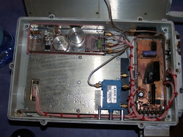
Condensation on the PA block and evidence of a fire!
So It was back up onto the roof, this time to retrieve the sick transverter complete with all the cables. Initially the damage wasn’t immediately evident, although the amount of moisture on the PA block, obviously condensation, was worrying. The DB6NT transverter showed absolutely no signs of water ingress. Then I lifted the lid of the PSU unit. It was clear there had been a fire. The DC-DC converter providing the -12V rail looked like it had exploded and burst into flames. See the close-up below.
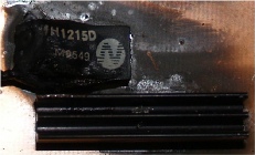
Totally destroyed NMH1215
The obvious question was ‘what was the most likely cause of the failure?’ The maximum current that the NMH range of DC-DC converters can deliver is 60mA per rail. Ideally I should have used an NMS1212 (84mA per rail) but I had an NMH1215 in stock, so I stepped the -15V output down to -12V via a regulator. The NMH1215 showed no signs of distress during testing. However it is likely that with the feed-through terminals latterly sitting in water, that extra current was drawn from the -12V line, over and above that which the PA requires. This extra demand may well have over-stressed the device resulting in a spectacular catastrophic failure. Fortunately there is a built-in fail-safe on the PSU board which automatically protected the PA. It is very clear that the structural integrity of the Ionica enclosure was suspect. It certainly had difficulty in fending of the Scottish weather, so I reluctantly opted to rebuild the entire system as a shack-based transverter. The coax run to the mast on the gable end is not too long so losses would be kept to a minimum. In stripping down the transverter I split the PA block so as to check for any signs of water ingress. Although there was no sign of direct water damage, there was a worrying amount of crystal growth on the inside of the milled aluminium lid. This had not been present before mounting the unit outside and was clearly the result of condensation. Looking back, and taking into account the size of the heat-sink and the amount of aluminium in the PA block itself, there would be a huge amount of thermal inertia involved. With temperatures at night dropping to close to zero Celcius, the PA block would require a lot of energy to warm it up. During the transmit cycle heat is produced, and since the PA block would be very cold, condensation would almost certainly be produced. This confirmed my decision to go for a shack-based approach.
Re-using the damaged PSU/Control unit was out of the question. The original design, on which I based my circuitry called for a relay to deliver the volts to the 10V regulator. I had replaced this relay with a high current MOSFET. In actual fact, there were two such devices in series since sequencing is provided by a DB6NT style sequencer. Each MOSFET has an on-resistance of only 60 milli-ohms. Without any extra heat-sinking, these devices are capable of dissipating around 1.5W. My calculations showed that the peak current would incur a peak power dissipation of around 3W, thus requiring a moderate heat-sink. This was achieved by mounting the devices at the board edge and wrapping two small sheets of copper over the edge to transfer the heat to the heat-sink. It isn’t very elegant but it works . . . the heat-sink gets noticeably warm, but no more than that.
Re-using the damaged PSU/Control unit was out of the question. The original design, on which I based my circuitry called for a relay to deliver the volts to the 10V regulator. I had replaced this relay with a high current MOSFET. In actual fact, there were two such devices in series since sequencing is provided by a DB6NT style sequencer. Each MOSFET has an on-resistance of only 60 milli-ohms. Without any extra heat-sinking, these devices are capable of dissipating around 1.5W. My calculations showed that the peak current would incur a peak power dissipation of around 3W, thus requiring a moderate heat-sink. This was achieved by mounting the devices at the board edge and wrapping two small sheets of copper over the edge to transfer the heat to the heat-sink. It isn’t very elegant but it works . . . the heat-sink gets noticeably warm, but no more than that.
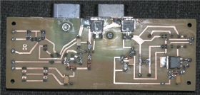
PSU/Cpntrol PEC, underside
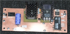
PSU/Control PEC, topside
The photograph on the right shows the finished transverter with the PA block and heat-sink mounted on the lid. A temporary S-shaped semi-rigid cable is used to link the output of the Ionica PA to the antenna change-over relay. When the box is closed, this cable is removed and a hole in the rear panel allows for the cable connecting the PA to the relay to be secured. The losses incurred as a result of the flexible cable between the DB6NT transverter and the PA can be ignored since a variable attenuator is already required to bring the drive level down to around 0.5mW.
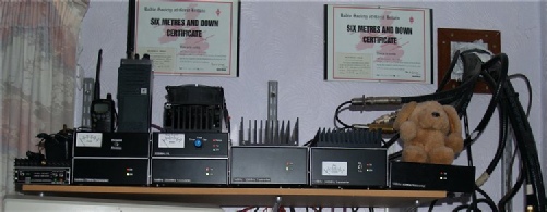
I need a bigger shelf now! Left to right - 2m linear (80W), 4m (30W), 13cm (50W), 23cm (30W), 9cm (15W), 70cm (10W) and Bobby
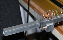
QLY feed point