The Wadley Loop Explained
2 minute read
March 2009
 RA17 Wadley Loop
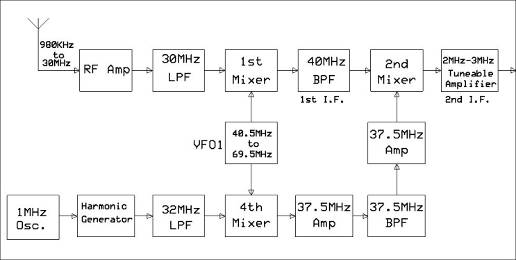
To be honest, I’m not convinced that what we call a Wadley Loop is actually a loop. However it is truly an elegant drift canceling design. Referring to the block diagram above, the 1st I.F in the RA17 is at 40MHz. This is achieved by having a 1st Local Oscillator which tunes from 40.5MHz up to 69.5MHz. This signal is fed simultaneously to the 1st and 4th mixers. The output of the 1MHz crystal oscillator (fc) is fed into a harmonic generator which produces a comb of harmonics (nfc), which is in turn fed through a 32MHz LP filter and then into the 4th mixer. Due to the bandwidth of the following 37.5MHz amplifier, as long as VFO1 (fo) is tuned to within 150KHz of one of the harmonics + 37.5MHz [i.e. (fo+nfc) MHz], there will always be a 37.5MHz product which in turn is then fed into the 2nd mixer via a 37.5MHz band pass filter and a second 37.5MHz amplifier. This is in essence the 2nd local oscillator. The output of the 2nd mixer is then fed into the 2nd I.F amplifier which is tunable over the range 2MHz to 3MHz.
VFO1 is little more than a simple LC oscillator and is therefore not necessarily drift-free; it doesn’t need to be. Any drift in VFO1 is by nature of the design, applied to both the 1st and 4th mixers. If the ‘Megacycles’ dial is set to 1 (MHz), VFO1 (fo) will be nominally 41.5MHz. In the 4th Mixer, this mixes with the 4th harmonic (nfc = 4MHz) of the 1MHz oscillator to produce 37.5MHz (fo - nfc). In the 1st mixer, an input signal (fs) at 1MHz is converted (fo - fs) to become 40.5MHz. Similarly, an input signal of 2MHz will be converted to 37.5MHz by mixing with the 5th harmonic (nfc = 5MHz) in order to produce a signal at 37.5MHz. (The bandwidth of the 1st I.F is 40MHz +/- 650KHz). Consequentially, any drift in fo is automatically compensated for in the operation of the 4th mixer.
Since it is not part of the drift cancelling loop, the third local oscillator (VFO2, ‘Kilocycles’) is not shown in the above diagram. This takes the form of a stable oscillator tunable over the range 2.1MHz to 3.1MHz and is injected into the third mixer immediately following the 2nd I.F amplifier. This is the final part of the conversion process resulting in a 3rd. I.F of 100KHz.