S-Parameter Test Set for the SDR-Kits VNWA
8 minute read
August 2016
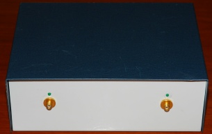
This was a project that I embarked upon simply for the fun of it. In fact, I don’t really need an S-Parameter Test Set; although I’m familiar with such things, having used one during my time with Racal. I had found a beautiful Transco Transfer Relay in my box of microwave odds and ends and was wondering what it would be useful for. As it happened, at about the same time there was some ‘chatter’ on the VNWA Yahoo Group which mentioned using a transfer relay to turn a VNWA into an S-Parameter Test Set. I downloaded several documents from the group and made the decision that I was going to enhance my VNWA by building it into an S-Parameter Test Set, not because I need one but because I could do it. The finished article is pictured on the right. I have left the front panel deliberately blank for the simple reason that I actually don’t know how to ‘identify’ the two connectors. I will explain as I go on.
With reference to the images on the left, I will try to shed some enlightenment on the transfer relay and how it is used to turn the VNWA into an S-Parameter Test Set.
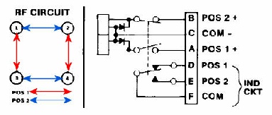
The top image is the schematic of the transfer relay itself. As you can see it has 4 connections. Since it is a coaxial relay, these connections are N-Type sockets and are numbered 1 thru’ 4. Unlike a conventional ‘failsafe’ relay which has one solenoid coil, this being a transfer relay, has two: One for each of the two positions. The connections for the two solenoids come out to pins A & B with C being the common. Pins D, E & F can be used as a position indicator. To assert Position 1, 28V DC is applied between A & C. Current flows, the relay activates and the current is automatically disconnected. The relay is said to be latched. In position 1, connectors 1 & 3 and 2 & 4 are connected. In position 2, connectors 1 & 2 and 3 & 4 are connected.
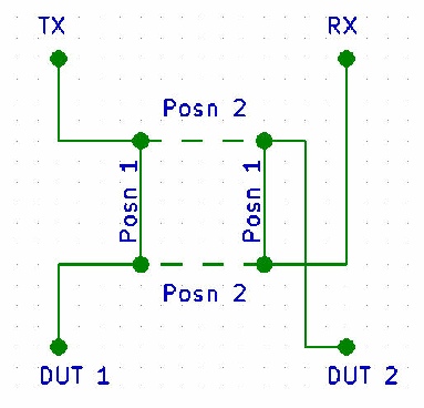
Now referring to the bottom image: TX & RX are the Output and Input ports on the VNWA whilst DUT 1 & 2 are the connectors on the Test Set for connecting the ‘Device Under Test’.
Note that when Position 1 is asserted, RF from port TX is fed through the relay to DUT 1. RF appearing at DUT 2 is then passed through the relay to port RX. This is essentially the same as connecting the Device Under Test directly to the VNWA. However with an S-Parameter Test Set it should NOT be necessary to turn the Device Under Test around in order to measure the S-Parameters in the opposite direction, and this is where the transfer relay comes in. When Position 2 is asserted, RF from port TX is now fed to DUT 2 and any RF at DUT 1 is fed to port RX ... Simple and elegant!
The original article describing how to use the VNWA in conjunction with two RF relays implied (correctly) that the relays could be controlled directly from the VNWA. The current software embodies support for using the VNWA in conjuntion with an external S-Parameter Test Set. However there are essentially three variants of the VNWA. The current hardware model is version 3, whilst I own a home-built model 2.6. The version 3 hardware has an RJ-11 connector on the rear which conveniently carries a control line which can, with appropriate circuitry, be used to activate a relay. There is no such connector on my VNWA. It took a bit of hunting but I eventually discovered that there is an output on the ATMega chip on the USB Interface board in my VNWA that can be used to control a relay. If you have an older, pre-USB VNWA, then there is a pin on the serial connector that will do the job.
Anyway, attaching a wire to the USB board looked easy enough, there is even a pad on the board for the wire. However, getting the wire out of the enclosure was not so easy. In the original article, and others have done the same, a 3.5mm jack socket had been fitted. I wasn’t keen on that idea since such connectors can be pulled out and I wasn’t happy with the idea that this might happen and maybe short the connection to 0V. Another solution was to use a stand-alone USB controlled switch to activate the relay. The schematic for this is shown below.
The top image is the schematic of the transfer relay itself. As you can see it has 4 connections. Since it is a coaxial relay, these connections are N-Type sockets and are numbered 1 thru’ 4. Unlike a conventional ‘failsafe’ relay which has one solenoid coil, this being a transfer relay, has two: One for each of the two positions. The connections for the two solenoids come out to pins A & B with C being the common. Pins D, E & F can be used as a position indicator. To assert Position 1, 28V DC is applied between A & C. Current flows, the relay activates and the current is automatically disconnected. The relay is said to be latched. In position 1, connectors 1 & 3 and 2 & 4 are connected. In position 2, connectors 1 & 2 and 3 & 4 are connected.
Now referring to the bottom image: TX & RX are the Output and Input ports on the VNWA whilst DUT 1 & 2 are the connectors on the Test Set for connecting the ‘Device Under Test’.
Note that when Position 1 is asserted, RF from port TX is fed through the relay to DUT 1. RF appearing at DUT 2 is then passed through the relay to port RX. This is essentially the same as connecting the Device Under Test directly to the VNWA. However with an S-Parameter Test Set it should NOT be necessary to turn the Device Under Test around in order to measure the S-Parameters in the opposite direction, and this is where the transfer relay comes in. When Position 2 is asserted, RF from port TX is now fed to DUT 2 and any RF at DUT 1 is fed to port RX ... Simple and elegant!
The original article describing how to use the VNWA in conjunction with two RF relays implied (correctly) that the relays could be controlled directly from the VNWA. The current software embodies support for using the VNWA in conjuntion with an external S-Parameter Test Set. However there are essentially three variants of the VNWA. The current hardware model is version 3, whilst I own a home-built model 2.6. The version 3 hardware has an RJ-11 connector on the rear which conveniently carries a control line which can, with appropriate circuitry, be used to activate a relay. There is no such connector on my VNWA. It took a bit of hunting but I eventually discovered that there is an output on the ATMega chip on the USB Interface board in my VNWA that can be used to control a relay. If you have an older, pre-USB VNWA, then there is a pin on the serial connector that will do the job.
Anyway, attaching a wire to the USB board looked easy enough, there is even a pad on the board for the wire. However, getting the wire out of the enclosure was not so easy. In the original article, and others have done the same, a 3.5mm jack socket had been fitted. I wasn’t keen on that idea since such connectors can be pulled out and I wasn’t happy with the idea that this might happen and maybe short the connection to 0V. Another solution was to use a stand-alone USB controlled switch to activate the relay. The schematic for this is shown below.
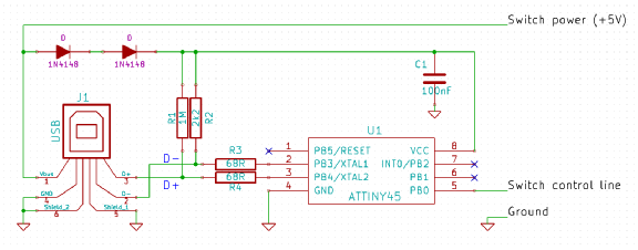
This is a tidy solution but it would require obtaining and programming an ATTiny45 microcontroller. More on that later.
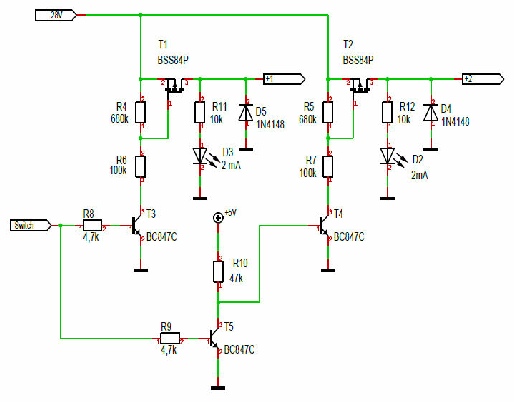
I even found Peter DC2PD’s article on using a latching relay as an S-Parameter Test Set. The schematic on the left is Peter’s relay driver circuit for use with the USB controller above.
Peter was even able to power his 28V relay from the USB port. I wasn’t so fortunate … more on that later too!
Peter was even able to power his 28V relay from the USB port. I wasn’t so fortunate … more on that later too!
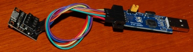
Programming the ATTiny45 got off to a faltering start. I’ve programmed PICs in the past but this little 8-pin chip posed a real problem. In theory a few wires from a PC Parallel port would work … but didn’t. I asked around if anyone could provide me with a pre-programmed chip. Then Stephen, G0XAR suggested I use an Atmel USBASP programmer to do the job. This in conjunction with a tiny board with an 8-pin socket and header proved to be a very cost effective solution. See below.
It looks like the most popular application for programming these devices is AVRDude. This is a command-line driven interface and so may not initially appear very user-friendly. However after looking at the GUI-based options, I opted to go for the steam-driven, Command-Line approach; and with a bit of help from this website I was able to program the ATTiny45 in a matter of minutes. The only issue that I encountered was due to the fact that the chip was not running an external crystal clock and was thus running much slower that the programmer. This issue is covered on the tutorial website.
Once programmed, the chip was soldered onto my USB-Switch PCB. See below.
Once programmed, the chip was soldered onto my USB-Switch PCB. See below.
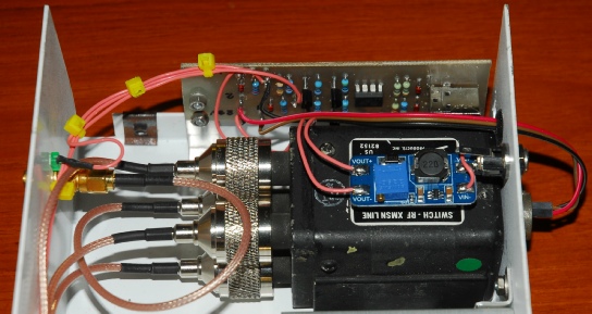
A tiny DC-DC converter sourced on Ebay is used to provide the +28V for the transfer relay. Unlike Peter, DC2PD, I wasn’t able to use the 5V from the PC’s USB port … even with a large reservoir capacitor … for two reasons. Firstly, my transfer relay draws 650mA when asserted. This is far too high for any USB port to deliver. Secondly, because the initial state of the relay is essentially unknown, it is possible that the controller will attempt to assert the relay the moment the software is run … in which case, any reservoir capacitor will fail to charge. So I opted to provide an external power source.
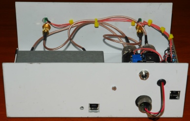
Note that the relay is actually too big for the box that I used! The control connector pokes out through a hole at the rear; hence the control lines from the PCB exit the box through a grommet and mini header sockets are used to interface directly with the pins in the Amphenol connector … seriously less expensive than buying the mating line-socket!!
And here it is … the completed S-Parameter Test Set. Left to right: USB-controlled switch, Transfer Relay, VNWA. Like the relay, the aluminium box was found languishing in a cupboard. The bulkhead mounted SMA barrels were salvaged from military kit, so are good quality. The green LEDs above the front panel SMAs indicate which one is currently the RF source.
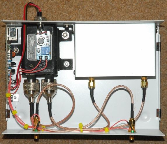
Note the use of two USB ports. There is a USB output connector on the VNWA but I have never been able to figure out how to use it … or if it can be used. I know that if I plug my ATTiny45-based USB device into it my PC reports it as an unidentified device and refuses to acknowledge the driver … hence the two USB ports.