Transmitter Type T.1154M Ser. 85660
19 minute read
April 2010
But first ... Some history ...
The T.1154/R.1155 Duo
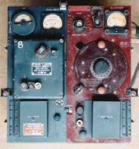
At the outbreak of WW2, the typical airborne communications equipment aboard RAF bombers such as the Wellington, Whitley, and Hampden, to name just three, was the R1082/T1083 combination manufactured by STC. This setup was already more or less obsolete with the majority of domestic receivers of the day being of a more sophisticated design. The R1082 was a basic regenerative design, and required the operator to change two coils in the set each time he wanted to change frequency range. Not only was this inconvenient and not exactly conducive to battle conditions, the type was also renowned for its unreliability. Like the R1082, the T1083, matching transmitter required the operator to swap out complete modules when changing frequency ranges. The black & white photograph below looks to me like the inside of a Wellington. The W/O is sitting on the left with the R1082 just visible in front of him. Above it is the T1083 with the two swapable modules, the unit with the two knobs on the left and the one with the single knob on the right. In effect, most of the transmitter was changed every time the operator changed band!. Whereas the receiver was entirely battery operated, the T1083 was powered from a dynamotor.
The STC R1082
By October 1939, after several disastrous raids which incurred massive losses, The Air Minstry (this is pre-Bomber-Command) had come to realise that communications between aircraft and base, as well as that between individual aircraft were much in need of an upgrade. With this in mind, a representative of the Air Ministry was dispatched to The Marconi Wireless Company. Marconi’s representative at this meeting was one of their senior design engineers, Christopher Cockerell, who would later go on to invent the hovercraft.
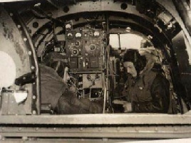
STC installation in a Wellington?
A contract was duly granted to Marconi to develop a new airborne communications package under the nomenclature T1154/R1155. The rest is history, ... as they say. Legend has it that Cockerell wrote the Air Ministry requirements on the back of an envelope. As early as 1930, Marconi had already developed the world’s first airborne transmitter based around a variable frequency master oscillator, the AD18. This type was subsequently refined over the ensuing years. Thus Marconi was well suited to the task at hand. Development of the new T1154 transmitter, based on the AD67 and AD77 transmitters was carried out by Marconi, whilst work on the R1155 receiver, developed from the AD68-72 receivers was jointly carried out by Marconi and E.K. Cole Ltd. (Ekco).
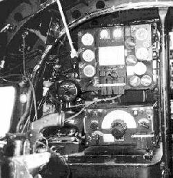
By January 1940, prototypes of both units had been successfully tested in flight trials and the new kit was being installed in all bomber command aircraft by June that year. This was a truly amazing engineering achievement. The photograph on the left gives an example of the new T1154 (top) and R1155 (bottom) configuration in a Lancaster. The iconic ‘Bathtub’ key is on the right of the W/O’s desk. This photograph clearly isn’t of an early installation since the R1155 sports the later Type 35 tuning mechanism, and a J-Switch antenna selector is clearly visible just to the bottom left of the T1154. Note also the unmistakable ‘pistol grip’ in the foreground, to the left of the receiver. This is a flare pistol which fired vertically downwards through a hole in the fuselage in times of emergency.
Same but different ...
T.1083
T.1154
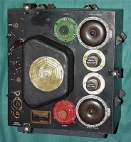
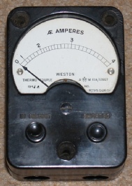
Unlike the R1155 which was predominately an all aluminium construction, the T1154 was largely of steel ... Presumably since it was rather heavy, weighing in at 44 pounds. However, like the R1155, the T1154 was not designed to be maintained since the life of a bomber could be measured in weeks ... Typically three! To highlight this fact, see the two photographs below. This is the external RF ammeter for the Fixed Antenna. This was mounted on the wall above the J-Switch, between the W/O and Navigator compartments.
T.1083
These little meters are quite rare and often fetch a high price on Ebay. I was very fortunate to get this example for the starting price! I was quite prepared for it to be faulty, so I was delighted when I discovered that it is still in working condition! What did take me by surprise though, was when I turned it over and found that it bore a significant amount of green paint ... The same colour as the inside of the bomber. It is therefore my belief that this little meter was fixed in place before the paint was dry! Such was the necessity to get the aircraft into service rapidly. Quite a poignant thought actually.
T.1154
Refurbishing my T.1154M
T.1154M before refurbishment
I got my T1154M from a friend who was keen for me to rebuild one of his three R1155s ... Or at least get one working one out of the three. He also had two, largely intact T1154Ms. I agreed to help him with his R1155, provided I got to keep one of the T1154s. That seemed a good deal to me! Unfortunately it was not possible to do anything with the three R1155 chassis. He finally got a fourth one, albeit missing ALL the key DF components. It has taken me over a year to collect all the missing pieces, but hopefully it will not be another year before another R1155 is brought back to it’s original glory.
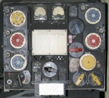
As for the two T1154Ms ... I felt it was only right to choose for myself the one which was least complete. Both the panel meters were missing as were all four of the valves. As can be seen from the photograph on the right, the paintwork was in a terrible state. The outside of the case looked as if it had been stored in a pool of water and such was the rust, it was some time before I was able to extract the chassis from the case! Quite a few of the Jones-plug pins had been soldered to and someone had previously made significant yet unfathomable modifications to the heater wiring. The valve socket for the modulator valve was shattered and the variometer had become separated from its spindle.
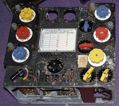
The first stage of any refurbishment process is always to remove and clean that which can be easily removed. In this case, all the knobs came off without too much difficulty. The coloured knobs appear to be some form of coloured Bakelite and clean up rather well. The cover plates over the Uni-Click mechanisms also come off easily. The panel for the meters comes off as does the panel behind the Master Switch. Both of these can be re-sprayed. Details of how this can be done giving it an almost authentic finish will be covered later. Since only one of the two transmitters had what I call a ‘front door’, I decided to make a second one. So pleased was I with my copy that I decided to keep it and moved the original onto the second transmitter. The one in the picture above is the original.
As for the two T1154Ms ... I felt it was only right to choose for myself the one which was least complete. Both the panel meters were missing as were all four of the valves. As can be seen from the photograph on the right, the paintwork was in a terrible state. The outside of the case looked as if it had been stored in a pool of water and such was the rust, it was some time before I was able to extract the chassis from the case! Quite a few of the Jones-plug pins had been soldered to and someone had previously made significant yet unfathomable modifications to the heater wiring. The valve socket for the modulator valve was shattered and the variometer had become separated from its spindle.
The first stage of any refurbishment process is always to remove and clean that which can be easily removed. In this case, all the knobs came off without too much difficulty. The coloured knobs appear to be some form of coloured Bakelite and clean up rather well. The cover plates over the Uni-Click mechanisms also come off easily. The panel for the meters comes off as does the panel behind the Master Switch. Both of these can be re-sprayed. Details of how this can be done giving it an almost authentic finish will be covered later. Since only one of the two transmitters had what I call a ‘front door’, I decided to make a second one. So pleased was I with my copy that I decided to keep it and moved the original onto the second transmitter. The one in the picture above is the original.
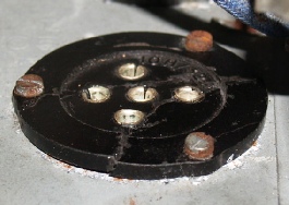
B5 base - before removal
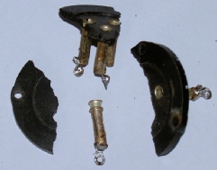
B5 base - once removed
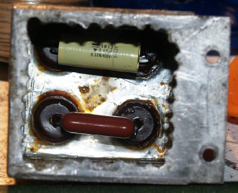
C21 and C8 (re-stuffed)
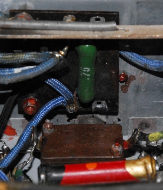
Unlike the R1155, the T1154 requires a minimum in terms of component replacement. Similarly, there should be no requirement to replace any of the wiring either. This is very fortunate given the transmitter’s construction which makes getting access to some of the central locations extremely difficult. There are only three capacitors which require instant replacing. One of these, pictured right is situated in the bottom left rear corner of the chassis. This is a compound block capacitor comprising C21 (0.5uF) and C8 (0.25uF). These values are actually stamped into the top of the capacitor. Curiously, this does NOT tie in with the manual, which states that both capacitors should be 0.5uF and gives the Stores Ref. No. As 10C/2053. However, T1154 variants A, B, D, E and J did have C8 as 0.25uF with the identical Stores Ref. A second T1154M, this time with Oct. 44 printed on the side of the block also has 0.25 and 0.5 stamped into the top of the can. Unfortunately in this case, the 0.25uF section is ‘leaky’ and the 0.5uF section is a dead short! I probably have to conclude that the documentation is out of date and trust the capacitor with the 1944 date code on it. Fortunately, these block capacitors are of aluminium construction and it is therefore very easy to drill a series of holes, making it possible to remove an unseen section of the can. I then drill into the foil capacitor at various points. This is extremely messy and results in mountains of foil and paper. I then gouge out the innards with a wood chisel. Sometimes, the bulk of the capacitor will come away all at once. The walls of the can will likely be lined with sheets of Paxolin. These can also be removed. When the can is more or less empty, it is a good idea to apply some heat from a heat gun and allow any residual wax to melt and run away. In line with the markings stamped into the can, in this case, one section of rolled foil was indeed twice the size of the other which would tend to confirm the values as 0.25uF and 0.5uF. It is then simply a case of soldering the new capacitors into the solder spills before screwing the block back into place. The other capacitor which will require attention is not so easy to access.
Carbon Mic-Bias Assembly
This is C26 (2uF), part of the bias circuit associated with the Carbon Microphone option. It is mounted on a sub-chassis along with LFC3 and R27/R28 (a compound wire-wound resistor) on the wall separating the PA compartment from the Modulator and VFO, above V1 and V4. Again there is a discrepancy in the documentation, which in Fig 11, shows LFC3 as being at the back, under S5 (Master Switch). This is actually T1, the input transformer on the modulator. To get this assembly out, it is necessary to remove all four valves. Then using a long screwdriver, remove the two screws retaining the rear top-cap assembly. This is necessary to gain access to the one counter-sunk screw. I also found it necessary to make my own very short screwdriver to remove the sub-chassis since there is no access in through the right side. Once all four screws are removed, the assembly can be carefully pulled forward. Note the corner which has been broken off LFC3. I don’t understand how I missed this at the time, but I was stumped as to why the modulator was not producing AM when the Master Switch was set to R/T. The clue was that there was no bias on the microphone. This particular T1154 had not been well treated. The socket for V4 had been smashed and it is likely that LFC3 had been damaged at the same time. Probably the reason I didn’t pick up on this fault earlier is the fact that the tag forming the junction between R27 and R28 was missing, as was the wire between that point and LFC3! Maybe if there had been a lose wire I would have spotted it? Fortunately the broken end of LFC3 was accessible and I was able to solder a wire onto it and link it to what was left of the damaged tag on R27/R28, thus restoring bias to the microphone.
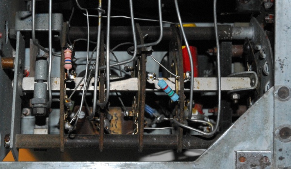
R14 and R25
The photograph on the left reveals yet another discrepancy. This time it is R25 in the Master Oscillator. The documentation calls for a 51R resistor, however in both T1154Ms in my possession, this is a 100R resistor. R14 is specified as 7.5K. For this I simply paralleled two 15K resistors.
R13
Tucked away under a bunch of wires on a small tag board, R13 (680R) is easy to miss!
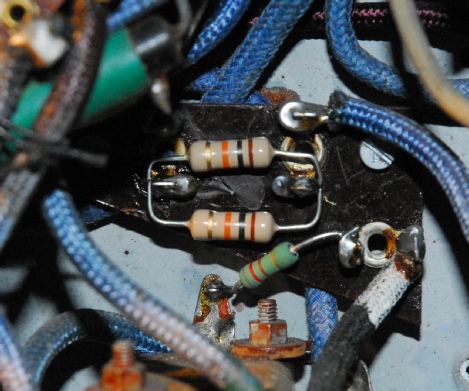
R24 and R15
R24 (5K1) and R15 (820R) are mounted on a curious triangular tag board at the back. Two 10K resistors have been paralleled to achieve something close to 5K1
R26 and R29
R26 (560R) and R29 (150R) are mounted on the band-change wafers.
These seven resistors are the only small carbon composite resistors that should require changing.
Filament Resistance Modification
If your T1154 sports an enigmatic and typed label pasted on the front panel stating ‘Filament Resistance Modification Incorporated’ ... like the one below, this is what it is referring to. In some cases, it might be two 1R5 resistors in parallel. In this case it is a single 0.75R resistor. This is essentially a power saving modification. When the Master Switch is set to STBI, the 6.3V heater supply is applied to ALL the valves in the T1154 and the R1155. Since the VT104s (PT15) PA valves each draw 1.3A, to save power, a 0.75R resistor is wired in series. This is switched OUT when the Master switch is set to TUNE, CW, MCW and R/T
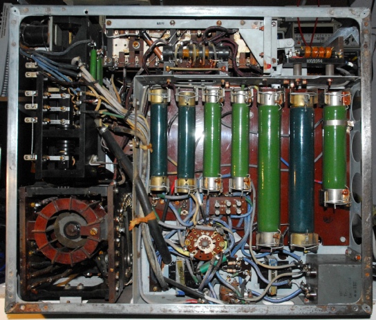
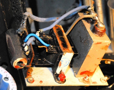
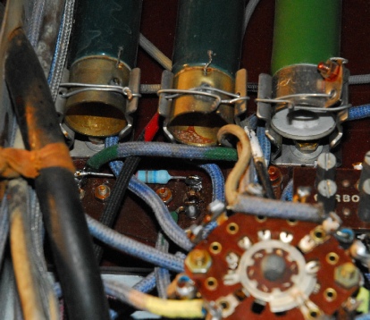
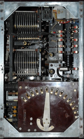
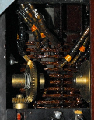
Two views of the inside of my restored T1154M.
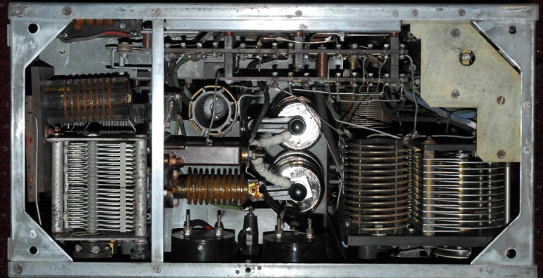
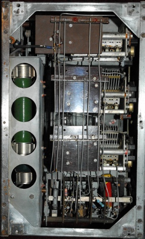
Two more views of the inside of my restored T1154M. The TX relay on the far right is a masterpiece of engineering which can cope with CW speeds of up to 25 w.p.m! ... apparently.
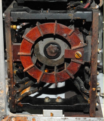
Two views of the variometer used for matching the PA to the trailing aerial on the MF (yellow) range.
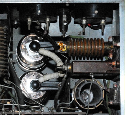
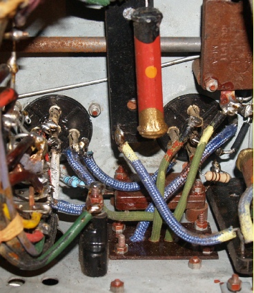
A close-up of the internals of the PA compartment.
I love the wave-wound inductors in the T1154. In the 50s and 60s when you could get your hands on one for a ‘tenner’, they were more often than not simply stripped down for the high quality inductors and variable capacitors.
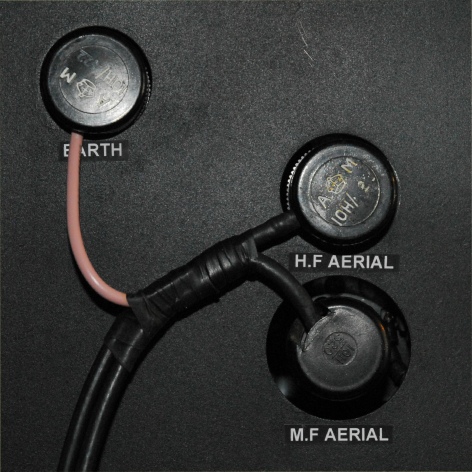
It goes without saying that the T1154 made use of some weird connectors. I was very fortunate to get my hands on these three (right). I had purchased something on Ebay and just happened to mention to the seller that I was restoring a T1154 and was looking for the matching antenna connectors. As it was, he had three left. So I made him an offer which was accepted. I’m not sure what I would do if I got myself a J-Switch ... I would need another five! ... And they are not necessarily all the same size either ... Not to mention the ones which fit the external aerial ammeter.
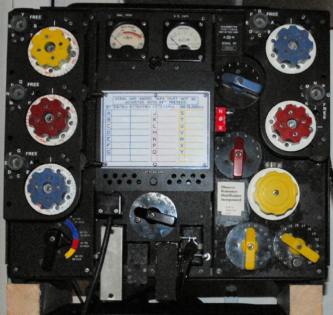 Fully restored T1154M Serial Number 85660
Most of the front panel lettering had been worn away, so I created new lettering from simple address labels by printing white on a black background. The blue on the Band Switch scale had all but gone, so I made a new coloured ‘arc’ which I printed on photographic paper to get an authentic finish. The lettering on the serial number plate was barely legible, so that too was recreated, as were the two labels to the left of the variometer. The Red-Range reversible socket (X-N) was missing, so I fashioned this from a block of MDF (sprayed matt-black), some rolled copper sheet and printed the label on photographic paper. The single-pin C-Shell connector for the 1200V was a lucky find on Ebay but commanded a premium price!! I am extremely grateful to Peter G0DRT who very kindly ‘donated’ the two missing panel meters to this project. Peter also let me have a pair of PT15s for a very reasonable price. These valves do come up on Ebay from time to time but are sought after by fanatical Hi-Fi enthusiasts who will pay silly money for them. They then strap all three of the grids together, run them as triodes and get about 15W of audio out of them ... Such sacrilege when some of us need them to restore these wonderful iconic transmitters. Sir Christopher Cockerell’s daughter said at the unveiling of a monument in honour of her father in 2010 (in relation to the hovercraft) that the T1154 and R1155 are thought to be the most important communications equipment in the life of the nation. She also said that her father had taken a flight in a Lancaster and had described it “…as near to hell as you can get, with the extreme cold, lack of oxygen and terrible noise level from the four Rolls Royce engines”.