A new 1MHz Osc. for the RA1217
7 minute read
March 2020
Some time towards the end of last year (2019) my RA1217 developed a fault. it always had a propensity to pop and crackle a bit, something which I attributed to the sheer number of germanium transistors inside. It was becoming noisier with time, so I slid it out from the rack, from between the RA1772 and the R-390, and prodded around with a plastic trim-tool. In the past, a sudden burst of noise accompanied with a drop in sensitivity was often rectified by a carefully aimed poke at the D-type connector on the end of the IF module: Not this time though. Instead, this time the culprit appeared to be the 1MHz Oscillator, or perhaps the cabling to and from the composite D-type serving it and the Harmonic Generator. Certainly moving the blue coax cables did appear to have an effect. I took the lid off the 1MHz module which also houses the Calibrator and a series of buffer stages. Examining the latter, I discovered that whoever had assembled the buffer board had ommitted to solder many of the 'liquourice-allsort' decoupling capacitors. So I spent some time carefully checking them all out and re-soldering where necessary.
But this didn't resolve the issue ... my RA1217 was still crackling and quite deaf. Then a lucky poke on the buffer board brought sweetness and light, or rather quieteness and good sensitivity. But it was to be short-lived, because in reality I had no idea what I had disturbed, and another poke, as suspected, was enough to re-instate the fault. The buffer board is a nightmare. It isn't a PCB like the Oscillator/Calibrator board. Instead it is a sheet of grp with all the components mounted between pins, some of which are double sided ... so there are components and connecting wires on both sides of the board. In order to check the integrity of the joints on the underside I was going to have to lift the board up and turn it over. This was not an easy task since some of the coaxes attach to the underside and this inhibits just how far the board can be raised. As it was, the wiring and soldering on the underside of the board was actually relatively good.
After several hours of testing, I was convinced that there was nothing wrong with the three stages on the buffer board. That left the oscillator stage which did appear to be delivering a somewhat low level of drive at 1MHz. The DC voltages all checked out good, so I replaced the transistor, a 2N3323, with another PNP germanium device to no effect at all. So I put the original transistor back. I even changed the crystal ... no difference! Finally I hit on the idea of using an external 1MHz source. I connected the 1MHz output from my MA259 to the External 1MHz Input on the rear of the RA1217 ... Bingo! Good sensitivity and no pops and crackles. So I left it like that until earlier this week. Having just completed refurbishing an RA17 MK2, an RA17L and an R1155E, I decided I had an opportunity do something for myself before the next RA17 came in for some TLC. At this point I had made the connection ... the gradual drop in overall signal to noise ratio was very likey symptomatic of something failing in the 1MHz oscillator.
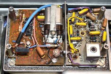
Left: My CMOS calibrator and original 1MHz Osc. Right: The Buffer board. (2010)
I replaced four of the decoupling capacitors on the Buffer board and almost all the components in the oscillator circuit to no beneficial effect. The drive into the tuned buffer stage was still pitiful. The waveform at the output of this stage was not a smooth sine-wave, but it was a 1MHz signal. With the external 1MHz signal applied, the waveform was similar but the amplitude was significantly greater. Disconnecting the buffer stage output from the Harmonic Generator had no effect on the amplitude or shape. I figured that since the object of the Harmonic Generator is to produce a signal rich in harmonics, the shape of the waveform at its input does not need to be sinusoidal.
At this point I made some changes to the component values in the oscillator circuit. I have two slightly different schematics. One has the original transistor-based regenerating divider calibrator and the other shows the later RTL-based digital divider. The capacitors in the output of the Pierce oscillator in this later schematic are different, so I gave these values a try ... absolutely no change! What was puzzling me was that the signal at the collector of the transistor (VT1) was a lovely clean sinewave of something like 12V p-p, yet the signal at the emitter was significantly less. I confirmed that there was nothing wrong with C3 (220pF). The output of the oscillator to the tuned buffer stage is a potential divider created by two capacitors between the emitter and ground. These two capacitors also provide a degree of feedback ... get these values wrong and the oscillator fails to start. With the oscillator board on the bench and with careful tweaking of these capacitors (C4 and C5) I was able to almost double the level of signal, but on connecting it to the tuned buffer stage, the drive level dropped due to the loading effect of the tuned buffer stage.
This stage is a bit of an enigma to me. On paper it is nothing special ... a simple amplifier with a tuned circuit in series with the collector. HOWEVER, the output is not taken from the collector of VT3 where there is a beautifully clean and large sinewave, but instead it is taken from the other end of L1/C11 where the signal is small and as previously said, a decidedly odd waveform. I actually tried taking the signal from the collector of VT3 (as an experiment) but the signal was 'killed'. So that maybe explains something.
I could have given up at that point ... pulled the crystal out and run with the external 1MHz supplied by the MA259 ... which, after all, is what the MA259 is designed for. Back in 2010, prompted by the discovery that both inductor cores in the calibrator were destroyed, I replaced the regenerating divider calibrator with a CMOS divider, as in the photograph above. Now with a crystal oscillator that was refusing to provide enough drive, I decided to replace the entire oscillator circuit with a monolythic one-chip solution.
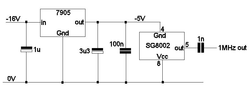
1MHz Oscillator using an Epson SG8002
The Epson SG2008DC (also known as Q3204DC21053300) is a 4-pin PDIP CMOS 1MHz oscillator designed for a 5V supply. Information on the datasheet is a bit scant. The device is described as programmable but comes with 1.0000 marked on the top. Pin 1 is normally left open-circuit for 1MHz out. Alternatively it (pin 1) can be used as OE (Output Enable) or ST (standby). The datasheet makes reference to an 'SG-Writer' which is available to purchase. So I have to conclude that under certain configurations the actual output frequency is prorammable (between 1MHz and 125MHz). As it comes, the output is a very nice 4V p-p square-wave at 1MHz. I initially thought about connecting a low-pass filter between the output (pin 5) and C10 on the input to the tuned buffer. Off-load it was possible to get a very nice clean sinewave but the high impedance nature of the filter resulted in a dramatic drop in level when connected to C10, so I threw caution to the wind and simply connected the output to C10 via a 1nF capacitor. It worked! My RA1217 was back working better than ever.
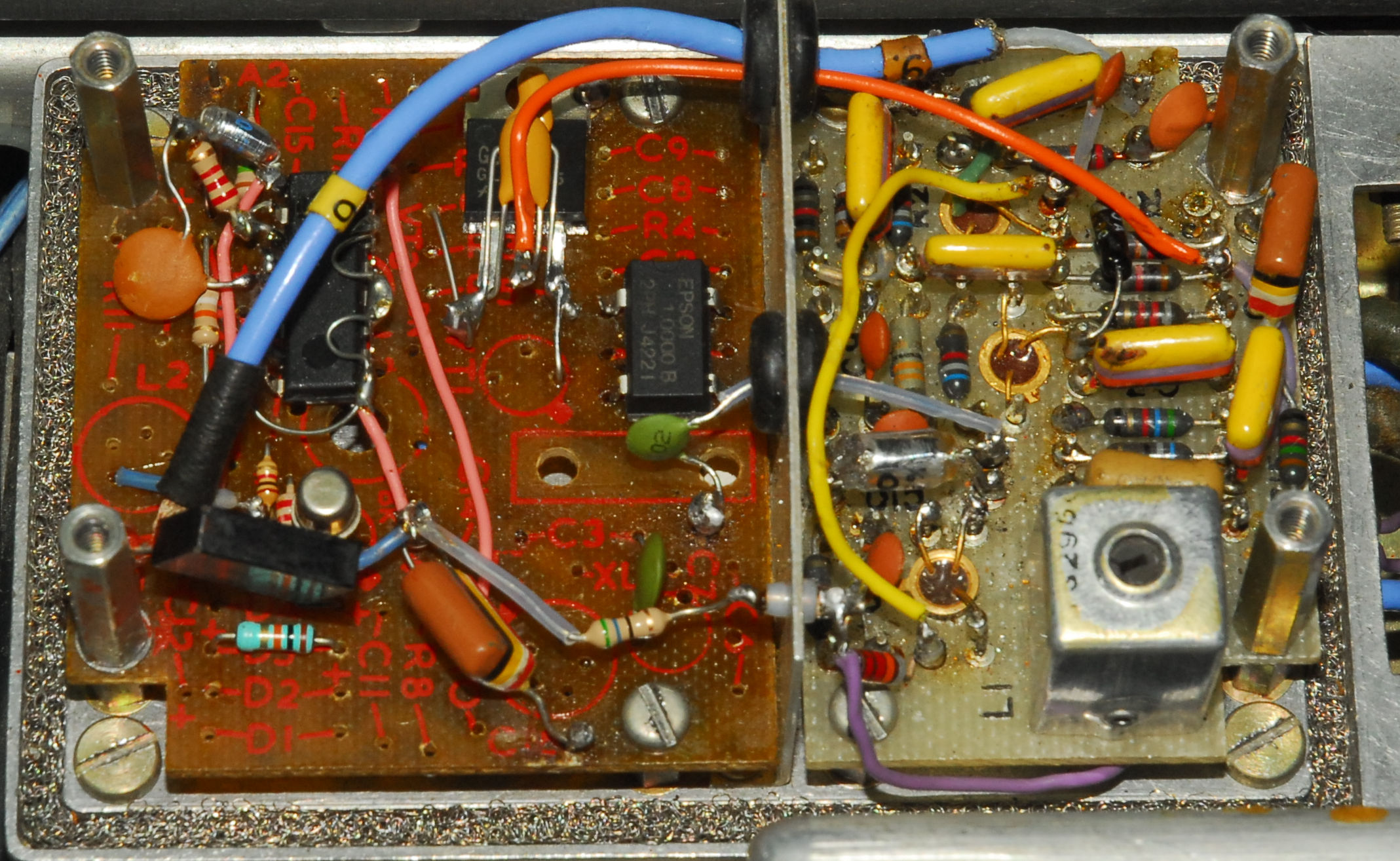
Left to right: CMOS divider-based Calibrator, CMOS 1MHz Oscillator, Original horrible Buffer board
My RA1217 is now nice and quiet. Gone are the crackles and other strange noises. The sensitivity is very good ... and I even managed to trace the gremlin associated with the D-type on the end of the IF unit. This turned out to be a dry joint on the 8KHz band-pass filter. Prodding the connector caused the filter mounting plate to flex, which in turn pulled very slightly on the wire-harness, causing the joint to flex ... enough said.