Refurbishing a Marconi CR100/2
34 minute read
This post is part of the series 'CR100':
Back in 1977, I was given a Marconi CR300 by one of my lecturers at college. Not the prettiest of radios but better than anything that I had owned up until then. Admittedly my experience with communications receivers up until then had been almost nil, consisting of an R1155 and a Halicrafters SX24 that had been re-valved with B7G valves. Neither of which worked particularly well. The 1155 probably worked better than the SX24 which had a tendency to go deaf after a few minutes. Had I known then what I know now, I probably would have fixed it in a few minutes, but back in 1977 valves were a mysterious black art to me. So when I was offered the CR300 I accepted it eagerly.
The CR300 was designed to operate from an external PSU, but at least it had a reasonable size front panel loudspeaker and someone had gone to the effort of building a power supply on a little chassis on the underside of the flip-up lid. It worked, and I marvelled at its ability to receive MSF Rugby on 60KHz. But, sadly, like the SX24 it was rather sick. It suffered from what almost all equipment from the 1940s was afflicted with … leaky decoupling capacitors. Like the R1155, the CR300 contained more than a couple of the tall iconic triple 100nF capacitors. And like in many 1155s, these were failing to the extent that they were no longer capacitors and thus the level of 50Hz mains-hum was terrible. Eventually I passed the CR300 on to my boss at Racal in the early 1980s. I believe he had some success with replacing a bunch of capacitors and managed to reduce the level of hum.
So when I was asked to give a CR100 a thorough ‘going over’, I thought “sure, I’ll give it a go … I used to have a CR300!”. Little did I know what I was letting myself in for. About the only thing that the CR100 shares with the CR300 is the shape … more or less a rather uninteresting cube.
 A bit of history … Always intended for the Admiralty, the origins of the CR100 date from 1939 when it was decided that the Royal Navy should be offered an alternative to the American HRO. Given that war in Europe was clearly an inevitability and with the signing of the Neutrality Act in the United States, I have to speculate that a ‘home-grown’ receiver was perhaps perceived as a necessity should the terms of the Neutrality Act result in a halt to the supply of HROs. Thus, in July 1939, design work began on what was to become the CR100 under the leadership of one Eric Zepler. Born Erich Zepler in Germany, Zepler had been chief of receiver design at Telefunken until leaving Germany to take up a position with Marconi in Chelmsford in 1935. This move was precipitated by the policy of racial persecution by the Nazi government at the time.
Unlike the R1155/T1154 combination which went from specifications on the back of an envelope (so the legend goes) to production inside three months, the work on the CR100 was less meteoric. The first experimental model was trialled in Portsmouth in the spring of 1940 and production of the first 500 receivers was undertaken in a converted chapel in Huddersfield a year later in the spring of 1941. Subsequently, main production was in Chelmsford. In all, eight variants (CR100/1 thru' 8) were produced. All variants with the exception of the CR100/2 were used in one form or another by the Royal Navy and given the designation B28, or in the case of the CR100/6 which was given B35.
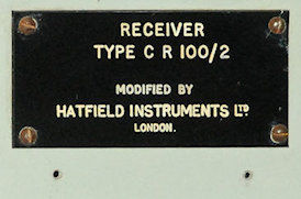
The version which I was handed is a CR100/2 … the RAF variant, which according to the manual has what is called a ‘Side-Tone Facility’, except it doesn’t, in the original sense since it has been modified. Neither does it sport any form of serial number since the original serial plate has been replaced by a slightly larger engraved plate identifying it as a CR100/2 that has been modified by Hatfield Instruments Ltd, London.
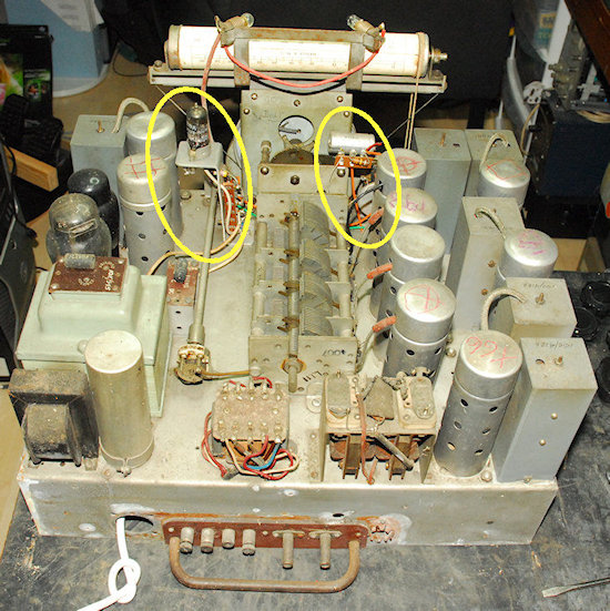
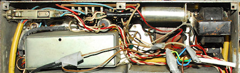
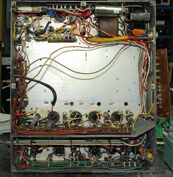
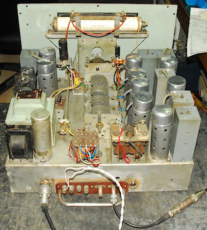
During its Service life there were several officially sanctioned modifications for the CR100. Marconi themselves, introduced their own ‘Radar Interference Suppression and Noise Limiting’ modification. In the photograph on the left, I have highlighted two obvious areas of modification. At first glance, the presence of the valve on a bracket looks like the Marconi modification, except the valve is a B7G 6D2 (EB91) as opposed to the IO VR54 (EB34) that Marconi used. Also, the bracket is taking up the space where R57 (part of the Side-Tone Facility) should be. So this is more than likely the Hatfield Instruments modification. Turning the receiver over, I found what appears to be a Mute relay that has been added. This is likely since R57 has been removed. The wiring relating to the HF (IF) Gain control has also been modified.
There were a couple of other divergencies from the original that I discovered that had me scratching my head. With these in mind, and keen to find out what the Hatfield Instruments modification was, I placed detailed requests for information on a couple of well-respected Internet sites. One of these has for years been a valuable source of information, either from available documents or from the vast collective experience of others. However this time the silence was deafening. This was most unexpected given the number of ‘threads’ relating to the CR100 on one of the groups. Could it be nobody knows what the Hatfield Mod is? Or could it be that the CR100 simply doesn’t have the fan-base that other classic WW2 receivers enjoy. Whatever the reason for the silence, and given the sorry state of the wiring in this particular CR100, I really had my work cut out. Almost all the wiring was going to require replacing, and being a stickler for authenticity it was important that the end result reflected Marconi’s original, coupled with Hatfield’s modification.
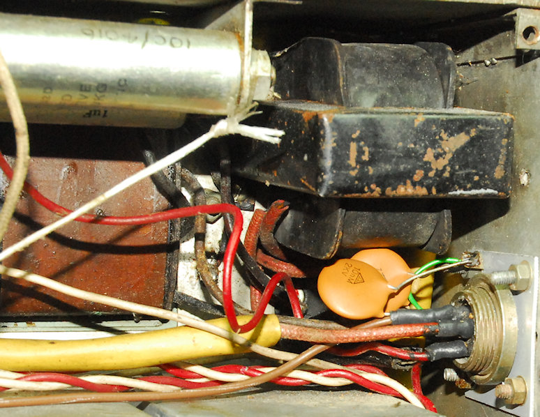
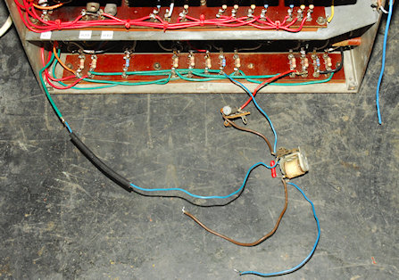
 The CR100 was designed to be powered from either 240V AC Mains or from external HT and LT DC supplies. Thus it had a 5-pin plug on the rear panel for this purpose. However the plug had been removed and a modern UK mains cord had been clumsily wired in its place with the DC input wires taped off. The front panel mains switch had also been replaced, or so it appeared. The mains cord had then at some point in time been cut off. There was no way I was going to attempt to power this receiver up without first rendering it non-lethal.
I have a box of old and curious vintage connectors. In it I found what looked just like the connector that had been removed. Sadly I didn’t have the mating flying socket, so I was going to have to be inventive when it came to getting power into the receiver.
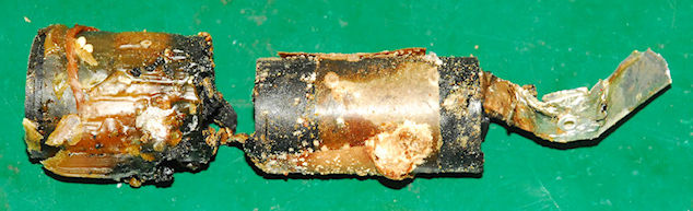
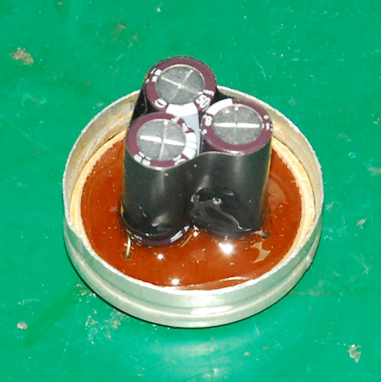
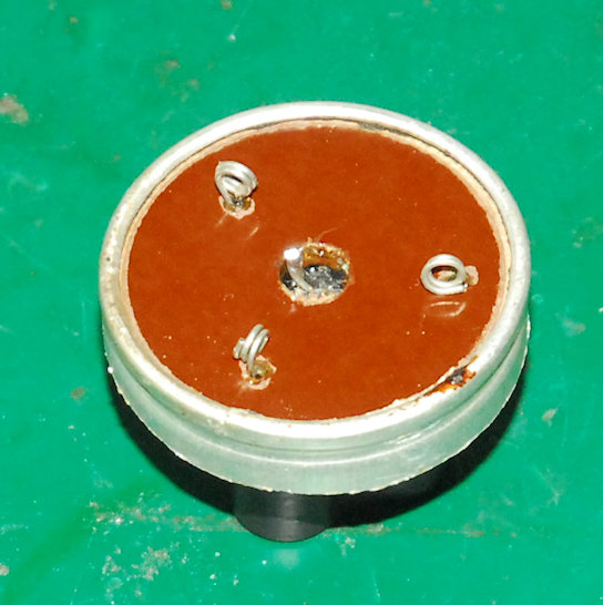
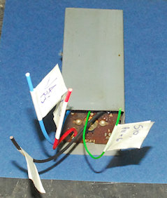
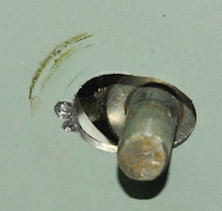
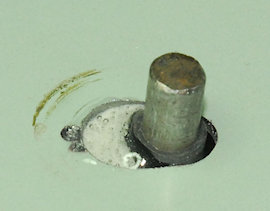
 Above: The re-birth of the 3 x 8.2uF/450V smoothing pack. See how tiny the modern aluminium electrolytics are. I cut a Tufnol disc to form the new base ... The original was disintegrating. In the original, the can was the common negative terminal. In the new pack, the can is isolated and a single common negative wire is brought out through a central hole.
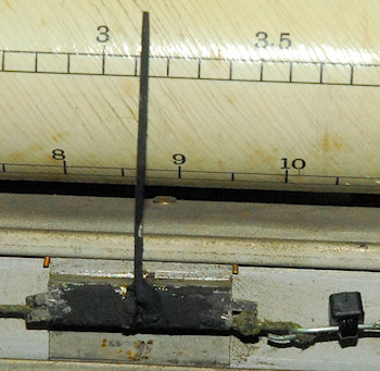
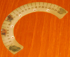 I think I can safely say that all photographs of CR100s that I have seen to date appear to show nice bright logging scales. The thing is, the logging scales are NOT lit. Very little light, if any, permeates down there from the two illumiation bulbs. This one however has suffered the dreaded celluloid shrinking problem. I think environmental conditions can exacerbate the issue, so this one may have been stored in a garage or somewhere where the temperature and/or humidity were prone to large variations. Not only were both scales yellowed, but the disc had shrunk so badly that it had warped (the top photograph illustrates this). The glue behind the crescent piece had also badly stained the piece. I was going to have a go at making new pieces until I learned that it was possible to flatten warped celluloid ... so I gave it a go.
 To flatten the celluloid I heated up one of our ovens and a solid baking tray to about 75 degrees Celcius. I then placed each piece face down on the tray with a heavy copper sheet (pre-heated) on top as a heat-spreader and placed a couple of heavy steel blocks on top then put the whole lot back in the oven for about 5 minutes. Once out of the oven I placed a heavy granite mortar on top and waited until the tray had cooled to room temperature. It worked! Both pieces are nice and flat again.
Obviously I had to drill out the tiny rivets to remove the celluloid pieces. Re-fitting is quite simple. All I did was tap each hole in the metalwork to M3 and then very carefully counter-sink the matching holes in the celluloid. I did have to elongate the holes in the disc to compensate for shrinkage. I then cut down some small-headed counter-sunk M3 screws such that the threads did not foul on any other moving parts once the celluloid pieces we re-attached. I had to move the disc assembly very slightly, but it is all back together and the tuning mechanism action is super-smooth.
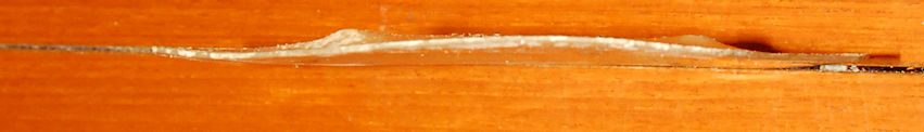
Left: Flattened celluloid pieces re-attached.
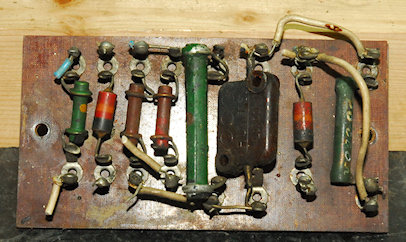
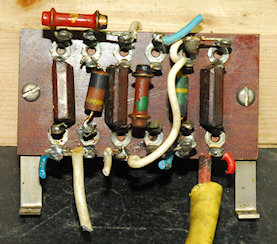
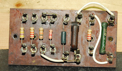 Above and below: The BFO and detector circuits are more or less contained within a screened box as seen in a previous photograph. Oddly, the components are split between two tag-boards ... the smaller one inside this box, the larger of the two, outside. Here we have before and after photographs of both these boards.
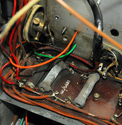
Left: Then I discovered this. With the larger of the two tag-boards removed from the side wall, and the two ‘phones jacks removed, I noticed a bunch of severed wires poking out from the wiring loom that runs between the front and back of the receiver. This passes through a couple of lengths of now brick-hard plastic.
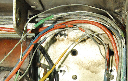
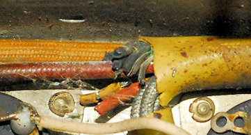
Right: Another view of the six severed wires with the horrible yellow sleeving cut away. All six wires had then been cut again in the area adjacent to the rear panel terminals. The 1940s rubber insulation had perished and turned to dust. Maybe this was why they had been cut. Maybe these were the original wires between the ‘phones jacks, the audio stage (KT63) and the output transformer at the rear. If that were so, the wires were definitely cut a long time ago since the current audio wiring is definitely not new.
 Above: The offending rotten wires removed. Just about to fully gut the compartment.
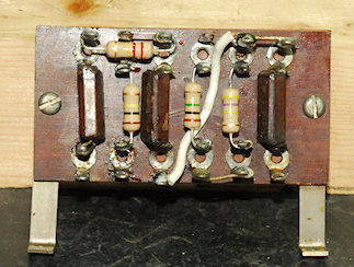
Below: The fully refurbished compartment ... minus the metal screen.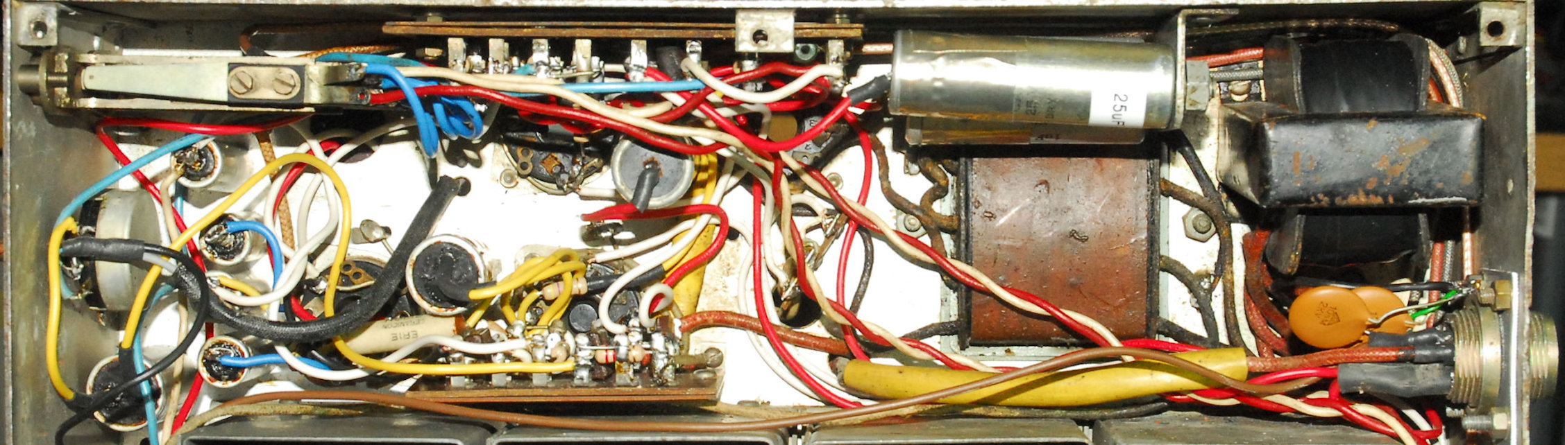
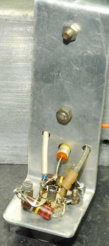
As mentioned previously, the front panel bears a label stating that this CR100/2 was modified by Hatfield Instruments. The CR100/2 was used by the RAF primarily and to a lesser degree by the British army. RAF stores numbers can be found everywhere inside the receiver. The CR100/2 is unique in that it came with what was termed a Side-Tone Facility which the manual says can be used to mute the receiver in the presence of strong signals. The way it works is very simple. Under normal receive conditions, R57 is shorted out and the gain of the IF stages is as per that set by R41, which sets the gain by varying the level of positive bias applied to the cathodes via the 'Cathode line' in excess of the normal self bias developed across the individual cathode resitors. Use of the Side-Tone-Facility brings R57 into play each time the transmitter is keyed, effectively increasing the positive bias further and thus muting the receiver. The level of muting can be set by the operator such that they hear their own 'Side-Tone' at an appropriate level. However this one has been modified and the Side-Tone Facility has been butchered/removed. Where R57 should be, there is a small metal sub-chassis (see left) with a B7G valve socket containing a 6D2 Double-Diode. This little circuit is inserted between the triode section of V8 and the main audio stage (V9). Also, the Side-Tone Facility socket has been re-wired so that it now goes to the solenoid of what is clearly a retro-fitted Muting relay which is wired to the 'Cathode Line'. The HF-Gain control (R41) wiring does not conform to the schematic.
I was not happy with the B7G socket ... The valve was very loose, so I decided to re-build this little circuit and figure out what it did.
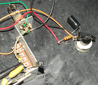
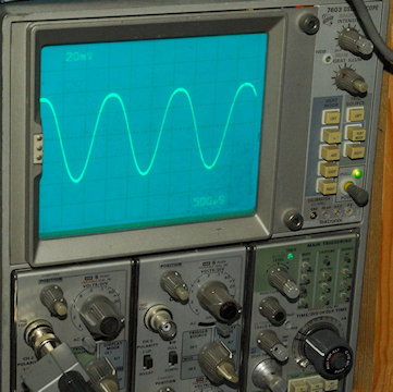
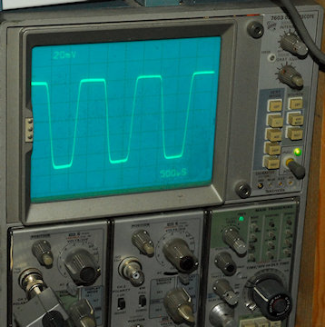
Right: The re-built mystery circuit on the bench undergoing test. This is a beautifully elegant and effective limiter circuit. Because the diodes are connected anode-to-anode, both top and bottom portions of the incoming waveform are clipped. The potentiometer sets the bias current and thus the voltage across the diode and thus the level of clipping. In other words the maximum level of signal into the KT63 can be limited. See the photographs below. Here I set the limiting to keep the peak-to-peak amplitude to 2V. Note how the less than 2V pk-pk sine-wave remains a sine-wave but as soon as it is increased to greater than 2V pk-pk the peaks and troughs are clipped. Obviously this will have a seriously detrimental effect on certain types of signal by adding distortion but it is an effective way of limiting the effects of strong interference.
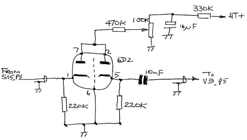 Limiter circuit schematic
So what about the other wiring anomalies? I ended up doing this ...
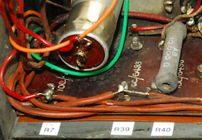
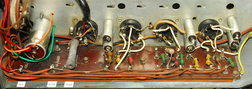
A lot of thought has obviously gone into the construction of the CR100 such that the entire coil-box assembly can be easily removed. I had been going round in circles getting nowhere trying to figure out the wiring around R7, R39 and R40. Now I could see exactly what was going on. It looked like R40 which should be 10K, was measuring 18K and was seriously cooked too. It was also wired to the Frequency Changer coil-pack!! So it would seem. Also, it appeared that the wires to R7 and R40 had been swapped too.
Left: Coil-box removed from chassis with screen around aerial pack removed for easy access.
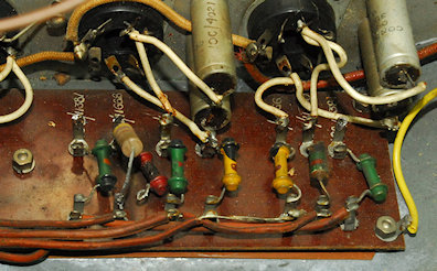
Below: Finally ... There be nasties in here!. On the left R7, seriously cooked. Whilst on the right, we have a partially disconnected burned-out red resistor and an ugly repair job. This is R13, the anode resistor in the RF amplifier stage.
 The resistor mystery is solved! I eventually found a note on page 14 of the manual stating that on early models, the placing of R7 and R40 is swapped! I should have realised that this particular CR100 is a very early model, in which case, resistors R7 and R40 are indeed in opposite positions. Confirmation of the early date of this receiver is reinforced by the fact that almost all the carbon resistors are the early solid bar type with values not corresponding to the now standardised E12 series. Interestingly, the manual (No. T1868/1) lists both the original value and the closest E12 value for each resistor.
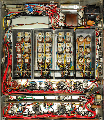
 With the coil-box removed from the chassis, it made perfect sense to investigate and replace any ‘at risk’ components in the sub-assembly. The shield around each compartment comes off easily, making the job all that easier. In total, three resistors and four decidedly 'iffy' 100nF capacitors were replaced. The latter (below) were oozing a nasty oily waxy substance.
Left: I believe the reason for swapping R7 and R40 was to make it easy to access the ‘far’ end of R7 which is otherwise obscured by capacitor C78 in early models. This end of R7 goes to a wire in the coil-box, and since the latter is designed to be easily removed it makes perfect sense to NOT obscure one of the solder-joints. Note the cloth-covered wire at the far end of R40. This was originally connected to R41 (HF Gain) but is now wired directly to 0V. This will be discussed later.
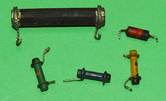
Right: The big black resistor is the original ‘cooked’ R7 which should be 20K and rated at 3W. It is so over-heated that all the paint has flaked off and it now measures 18K. I have replaced it with a modern 5W carbon 22K type. The other resistors in the photograph serve to give an idea of the different types used. Each one pictured is non-E12 series.
However, resolving the issue with R7 and R40 still left the question of the odd cloth covered wire between R40 and chassis via a pin on V4 (see above). According to the circuit diagram, that end of R40 should go to the HF (or RF) Gain control (R41) as in the diagram below.
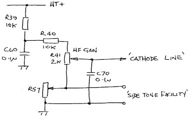 Left: In this circuit, the gain of the RF stages and the first two IF stages is controlled by varying the positive potential of what the manual calls the ‘Cathode Line’. In the CR100/2 however, R57 comes into play and further increases the potential on the Cathode Line, further reducing the gain ... Essentially a ‘MUTE’ facility.
Note: The junction of R39 and R40 provides the Screen Grid voltage for all the RF and IF amplifiers. Thus each time the 'Side-Tone' terminals are opened, not only does the potential on the Cathode Line increase but the Screen voltage will also increase. Is this a problem, I wonder?
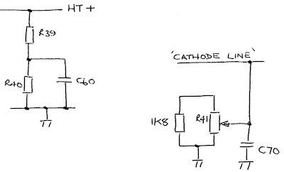
However, R57 is missing ... Its physical space is now taken up with the ‘Hatfield Instruments modification’. R40 no longer goes to one end of R41 and is instead now wired to 0V (Chassis), thus ensuring a constant Screen Grid voltage to the RF and IF amplifiers. The HF Gain Control is now reduced to nothing more than a variable resistor between the ‘Cathode Line’ and 0V. A 1K8 resistor has been added in parallel with R41 reducing the effective resistance to approximately 950 ohms.
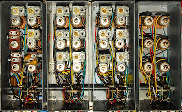
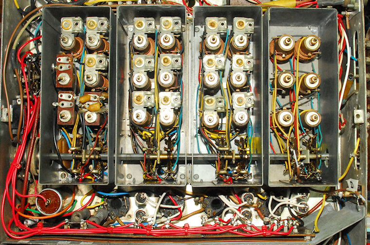
A curious design feature of the CR100 is that although the mixer stage employs an VR99 Triode-Hexode (aka X65 or ECH35), a valve specifically designed as a Mixer/Oscillator ... Only the Hexode part of the valve is used (as the mixer). The Triode section, normally employed as the Local Oscillator is not used. Instead a KTW61 (or VR100) forms the Local Oscillator. The manual says that this valve is operated as a Triode, but in actual fact the configuration is more akin to that of a Tetrode since the Screen and Suppressor Grids are ‘tied’ together and connected to the Anode. There is no explanation in the manual as to why a separate valve is used for the oscillator but it may be a way of attaining a higher level and possibly more stable Local Oscillator signal whilst at the same time minimising any unwanted mixing products.
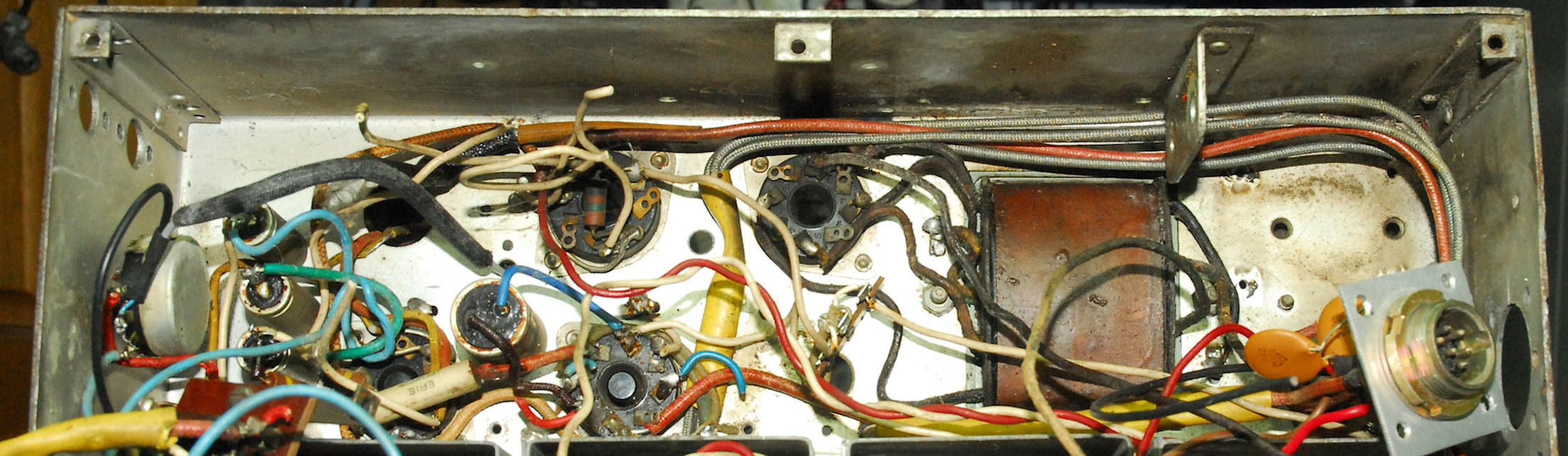
 The RF, Mixer and Oscillator stages prior to refurbishment.
In the photograph above, the valve line-up is, from right-to-left ... 1st RF Amp, 2nd RF Amp, Mixer and finally the Local Oscillator. All the tubular capacitors in this area have been re-stuffed.
The RF, Mixer and Oscillator stages prior to refurbishment.
In the photograph above, the valve line-up is, from right-to-left ... 1st RF Amp, 2nd RF Amp, Mixer and finally the Local Oscillator. All the tubular capacitors in this area have been re-stuffed.
So, having finally figured out what was going on with R7, R39 and R40, we could then proceed with the refurbishment of the RF and IF stages.
 RF Amplifiers, Mixer and Local Oscillator after refurbishment.
The photograph above shows V1 thru’ V4 stages now fully refurbished, including another 7 re-stuffed metal-can capacitors. The coil-box is now back on the chassis. The High-Z input to the 1st RF stage was found to be missing and has now been restored.
RF Amplifiers, Mixer and Local Oscillator after refurbishment.
The photograph above shows V1 thru’ V4 stages now fully refurbished, including another 7 re-stuffed metal-can capacitors. The coil-box is now back on the chassis. The High-Z input to the 1st RF stage was found to be missing and has now been restored.
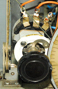
The IF Transformers are relatively easy to re-wire since the wires attach to solder-tags in a convenient recess space on the underside. The enclosures are tin-plate and thus soft and prone to damage (see later). The one pictured on the left is the 1st IF Transformer.
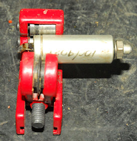
The photograph on the right shows how I use a simple pipe-cutter to open the tubular stud-mounting capacitors.
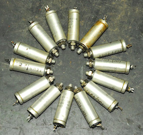
And on the left, here we have the final batch of 14 stud-mounted 100nF capacitors, re-stuffed with 630V polypropylene capacitors, awaiting refitting in the final part of the CR100 ... around V5, V6 and V7.
Right: The new resistors and re-stuffed capacitors in place. But what to do about that relay and the little tag-strip? Actually I am not convinced that his was added by Hatfield Instruments. The tag-strip used for the potential divider is identical to that used in the limiter circuit but the insulation used to sleeve the joint between the green and blue wires has definitely been culled from a length of coax ... Inventive but not exactly professional. However I decided to keep the circuit since, on paper, it appears to be a clever muting circuit. The schematic is shown below.
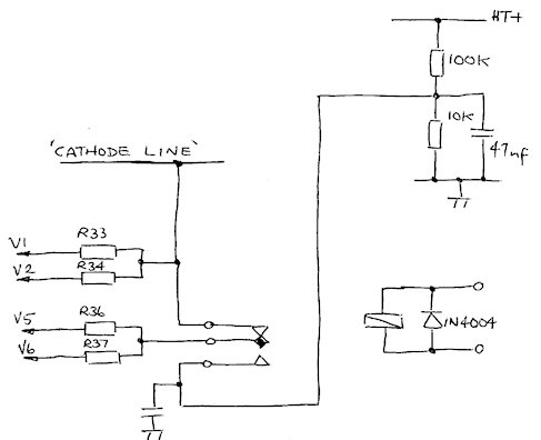
How it works: The potential divider provides a nominal +25V level. The relay actuator coil is connected across the Side Tone Facility terminals ... 12V appears to be sufficient to operate it. When not energised, all four cathode resistors are connected to the ‘Cathode Line’. When the relay is energised, resistors R36 and R37 are instead connected to the +25V from the potential divider ... Effectively turning V5 and V6 off and thus muting the receiver.
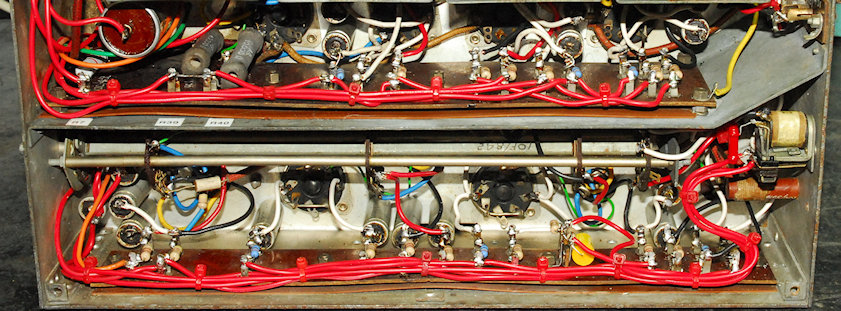
Below: All the wiring associated with the valves is now complete. The Mute relay was previously attached to the rear wall of the chassis by one of the self-tapping screws that secured the cabinet to the chassis. To me this was another reason for discounting this as part of the Hatfield Instruments mod since there are two 6BA tapped holes provided on the relay. I drilled two counter-sunk holes in the chassis and mounted the relay as per the photograph. Now when the cabinet is removed, the relay does not fall inside!
 All RF and IF stages complete.
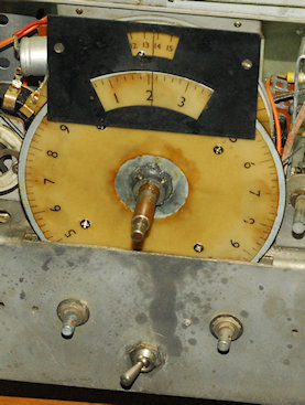
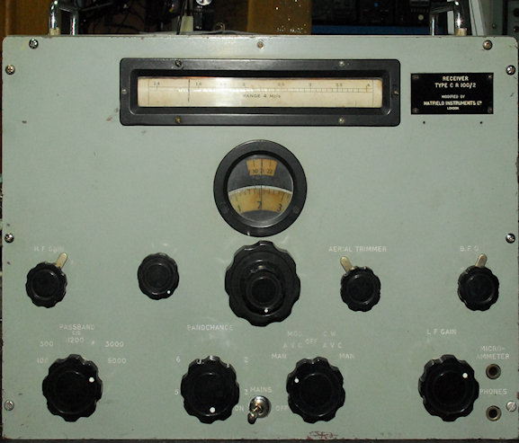 Left: The front panel now back in place. Four of the knobs have metal pointers ... three rounded and one pointed with the large pointed one fitted on the band-change control. However on this one the pointer was significantly offset from the white dimple. I looked at the other large knobs and found that on some of them, the brass insert onto which the pointer was fitted, was actually as much as 10 degrees out. But I did find one which did line up, so I moved the pointer over to that one. However it does look like something was missed in production so that the white dimple was NOT lined up with the three holes at the back. I don't think I've seen photographs of CR100s with rounded metal pointers (common on the R1155) on the HF Gain, Aerial Trimmer and BFO controls. It was however Marconi's policy at the time to use parts already in production for other equipment ... makes a lot of sense.
 Above: Two views of the inside of the refurbished CR100/2. I'm happy with the way it looks, although not as 'pretty' as an RA17. All adjusment points are accessible at all times. Even the Plessey connector does not look out of place. The IF transformer, bottom right in the right-hand photograph had taken a knock at some time and the soft thin tin had actually torn where the rivets held the 4BA studs on. This made it impossible to secure it tightly to the chassis. I fixed this issue by drilling out the old rivets and fitting new pop-rivets with a washer either side. This way the rivet pulls the two washers tight up against the wall of the transformer case. The IF transformer is now tightly secured to the chassis. The two aerial connectors are very unusual. These are MUSA connectors, favoured by the GPO and the BBC back in the day. Off course, coaxial cable was a very new thing in the early 1940s, so there was no 'standard' for suitable connectors. Manufacturers like Pye and Burndept came up with their own, as seen on the 19-Set and RA17 etc. And then there's the good old Belling-Lee! It would be easy therefore to suggest that the MUSA connector was yet another British 'go-it alone' invention, but it looks like it might have been developed by Bell Laboritories. I went looking for MUSA connectors and found one enterprising seller asking nearly £70 for a MUSA-to-BNC adapter! I then found someone else selling various MUSA connectors and adapters for around £10 each. I know where I would go if I ever need one. However I managed to make a pretty good connector out of a humble Belling-Lee plug!
So it was now time to perform a 'controlled power up'. For this I planned to remove the rectifier valve and apply HT and LT from my variable HT supply that I use when testing RA17 VFOs. This would allow me to avoid nasty surprises. But first I went through all the resistance checks listed in the manual. Confident that there were no short circuits, HT+ and Heater volts were applied and slowly wound up to 250V. Apart from what turned out to be little more than dirty contacts on the Operation Switch, the CR100 worked first time. On the whole, frequency accuracy wasn't bad with the exception of Band 6 where everything was slightly to the 'right'.
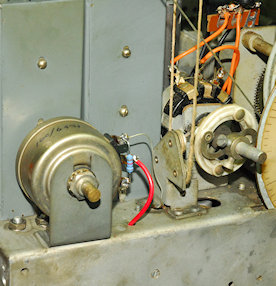
Running through the alignment procedure for the coil-box, I found an error in the manual. In figure 22 on page 55, tuned inductors H.F.3 and H.F.4 are swapped. Everything peaked up nicely although the frequency accuracy at the top end of each band is a little bit out. The Local Oscillator was a tad stubborn to start on Band 4 ... another dirty contact issue, so the can of De-Oxit came out again. As I was rocking the band-switch back and forth the drive-cord for the drum came off! Unlike the cord for the pointer, the one for the drum was more like parcel-string! This is quite aparent in a couple of previous photographs relating the the HF Gain and Limiter controls. Fortunately I have a roll of proper drive-cord. The manual has some excellent instructions for re-stringing the two drive-cords and it was here that I learned that this CR100/2 may not be as early as first thought, as it has the later 5-pulley system for rotating the drum. Re-stringing the drum cord is not something that can be rushed and an extra pair of hands does help.
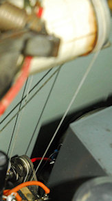
The photograph on the left shows the new drum drive-cord.
 I was also concious of the fact that there was some unwanted slack on the Pointer drive-cord which resulted in a bit of 'lag' as the slack was taken up before the pointer moved when the tuning was adjusted. I had a think about this. Did I want to go through the whole re-stringing procedure with this cord too? What if I could take up the slack without actually disturbing the existing cord? I noticed that the pointer never gets right to the end of the 'track', in both directions. Thus there was room for what I had in mind. The amount of slack wasn't a lot and I figured that a loop twisted into the cord would be enough, and it turns out that I was right. Here's what I did:
I took a small length (5cm) of 0.7mm steel wire and folded it in half such that the radius of the bend was about 1.5mm. I then placed it over the cord to the right of the pointer as in the photograph on the right. I then folded the ends over so as to complete the circle, as it were, and turned the loop such that it put a single twist in the cord. This was sufficient to take up the slack completely. One end of the wire was tied to the cord with a small cable-tie whilst the other was simply cut off. The stiffness of the wire allows for this. Copper wire would probably be too soft and un-wind. The slack is now gone. There is no longer any 'lag' when tuning, which is still silky-smooth. Job done!
I was not really too sure about the bandwidth settings ... there being little difference between 1.2KHz and 3KHz for instance. There's a whole raft of instructions in the manual regards performing the IF alignment which makes fascinating reading. Clearly Marconi were writing the book on receiver alignment based on their own in-house test equipment and some Cossor kit. What on earth is a ganging oscillator? I on the other hand have a network analyser. The only problem is that it is a 50-ohm instrument and care must be taken to NOT load (and de-tune) the circuits that you are attempting to align.
I eventually adapted a method that I use for 'shaping' the IF bandwidths in the RA17 series. I removed V4, the Local Oscillator and injected the sweep oscillator via 100nF to V3 pin 3. The analyser input was connected to the top-cap of V7, again via 100nF. Ideally I would have liked to connect it to the input of the detector but the metal screen around the detector circuitry was in place and since it is a real pain to fit I was NOT keen to remove it. So the alignment was going to be slightly compromised.
Unlike the RA17 series, the Bandwidths in the CR100 are a mix of IF and AF. The lowest 'real' IF bandwidth is actually 1.2KHz with 100Hz (and maybe 300Hz) being audio filters. I say maybe because I have not been able to find anything in the manual which specifically refers to the 300Hz position. According to the manual, IF alignment is carried out at 1.2KHz, which brings the crystal into play. Once you have identified the crystal 'response', IF1 and IF2 and adjusted to maximise the crystal 'response' whilst minimising any other response. This was easy to perform using my network analyser (as a wobbulator). There after, all other IF tansformers can be adjusted to maximise the crystal 'response'. (IF5 was later adjusted for maximum sensitivity). The manual is most clear that no adjustments should be made with the bandwidth set to 300Hz.
With the analyser disconnected and V4 re-fitted, the IF bandwidths all sound good with the exception of 300Hz, which sounds almost as wide as the 1.2KHz setting. The 100Hz audio filter is beautifully sharp. Looking at the circuit diagram, when 100Hz B/W is selected, S15 selects the Hi-Q band-pass filter formed by L62 and L63 etc. However, when the 300Hz B/W is selected, the filter is by-passed altogether. This would explain why there is negligible difference between the 300Hz and 1.2KHz bandwidths. ALSO ... remember that the Hatfield Instruments Pulse limiter is permanently connected between the output of the filter (S15 pin 5) and the audio output stage. The nature of this circuit must to a certain degree have an effect on the frequency response, albeit High-Pass in nature.
Connected to a high quality loudspeaker, the CR100 is surprising good on AM and CW. With judicious use of the HF Gain and BFO controls SSB doesn't sound too bad. With all its Rs and Cs replaced with modern types, the overall sensitivity is comparable with the RA17, with 20dB signal-to-noise being easily achieved for 1uV at the aerial input. The CR100 in general is said to be prone to VFO drift. However this one was remarkably stable with only a noticeable drift within the first 30 minutes from switch-on. If only my CR300 had performed as well as this!
Next post in the series: Refurbishing a Marconi CR100/1
- Refurbishing a Marconi CR100/2
- Refurbishing a Marconi CR100/1
July 2020
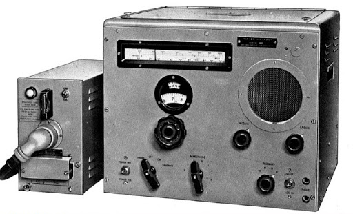
A CR300 with external PSU
Back in 1977, I was given a Marconi CR300 by one of my lecturers at college. Not the prettiest of radios but better than anything that I had owned up until then. Admittedly my experience with communications receivers up until then had been almost nil, consisting of an R1155 and a Halicrafters SX24 that had been re-valved with B7G valves. Neither of which worked particularly well. The 1155 probably worked better than the SX24 which had a tendency to go deaf after a few minutes. Had I known then what I know now, I probably would have fixed it in a few minutes, but back in 1977 valves were a mysterious black art to me. So when I was offered the CR300 I accepted it eagerly.
The CR300 was designed to operate from an external PSU, but at least it had a reasonable size front panel loudspeaker and someone had gone to the effort of building a power supply on a little chassis on the underside of the flip-up lid. It worked, and I marvelled at its ability to receive MSF Rugby on 60KHz. But, sadly, like the SX24 it was rather sick. It suffered from what almost all equipment from the 1940s was afflicted with … leaky decoupling capacitors. Like the R1155, the CR300 contained more than a couple of the tall iconic triple 100nF capacitors. And like in many 1155s, these were failing to the extent that they were no longer capacitors and thus the level of 50Hz mains-hum was terrible. Eventually I passed the CR300 on to my boss at Racal in the early 1980s. I believe he had some success with replacing a bunch of capacitors and managed to reduce the level of hum.
So when I was asked to give a CR100 a thorough ‘going over’, I thought “sure, I’ll give it a go … I used to have a CR300!”. Little did I know what I was letting myself in for. About the only thing that the CR100 shares with the CR300 is the shape … more or less a rather uninteresting cube.
Eric Zepler
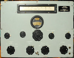
Modified CR100/2
Unlike the R1155/T1154 combination which went from specifications on the back of an envelope (so the legend goes) to production inside three months, the work on the CR100 was less meteoric. The first experimental model was trialled in Portsmouth in the spring of 1940 and production of the first 500 receivers was undertaken in a converted chapel in Huddersfield a year later in the spring of 1941. Subsequently, main production was in Chelmsford. In all, eight variants (CR100/1 thru' 8) were produced. All variants with the exception of the CR100/2 were used in one form or another by the Royal Navy and given the designation B28, or in the case of the CR100/6 which was given B35.
The version which I was handed is a CR100/2 … the RAF variant, which according to the manual has what is called a ‘Side-Tone Facility’, except it doesn’t, in the original sense since it has been modified. Neither does it sport any form of serial number since the original serial plate has been replaced by a slightly larger engraved plate identifying it as a CR100/2 that has been modified by Hatfield Instruments Ltd, London.
During its Service life there were several officially sanctioned modifications for the CR100. Marconi themselves, introduced their own ‘Radar Interference Suppression and Noise Limiting’ modification. In the photograph on the left, I have highlighted two obvious areas of modification. At first glance, the presence of the valve on a bracket looks like the Marconi modification, except the valve is a B7G 6D2 (EB91) as opposed to the IO VR54 (EB34) that Marconi used. Also, the bracket is taking up the space where R57 (part of the Side-Tone Facility) should be. So this is more than likely the Hatfield Instruments modification. Turning the receiver over, I found what appears to be a Mute relay that has been added. This is likely since R57 has been removed. The wiring relating to the HF (IF) Gain control has also been modified.
There were a couple of other divergencies from the original that I discovered that had me scratching my head. With these in mind, and keen to find out what the Hatfield Instruments modification was, I placed detailed requests for information on a couple of well-respected Internet sites. One of these has for years been a valuable source of information, either from available documents or from the vast collective experience of others. However this time the silence was deafening. This was most unexpected given the number of ‘threads’ relating to the CR100 on one of the groups. Could it be nobody knows what the Hatfield Mod is? Or could it be that the CR100 simply doesn’t have the fan-base that other classic WW2 receivers enjoy. Whatever the reason for the silence, and given the sorry state of the wiring in this particular CR100, I really had my work cut out. Almost all the wiring was going to require replacing, and being a stickler for authenticity it was important that the end result reflected Marconi’s original, coupled with Hatfield’s modification.
The work begins ...
I have a box of old and curious vintage connectors. In it I found what looked just like the connector that had been removed. Sadly I didn’t have the mating flying socket, so I was going to have to be inventive when it came to getting power into the receiver.
New Power Connector
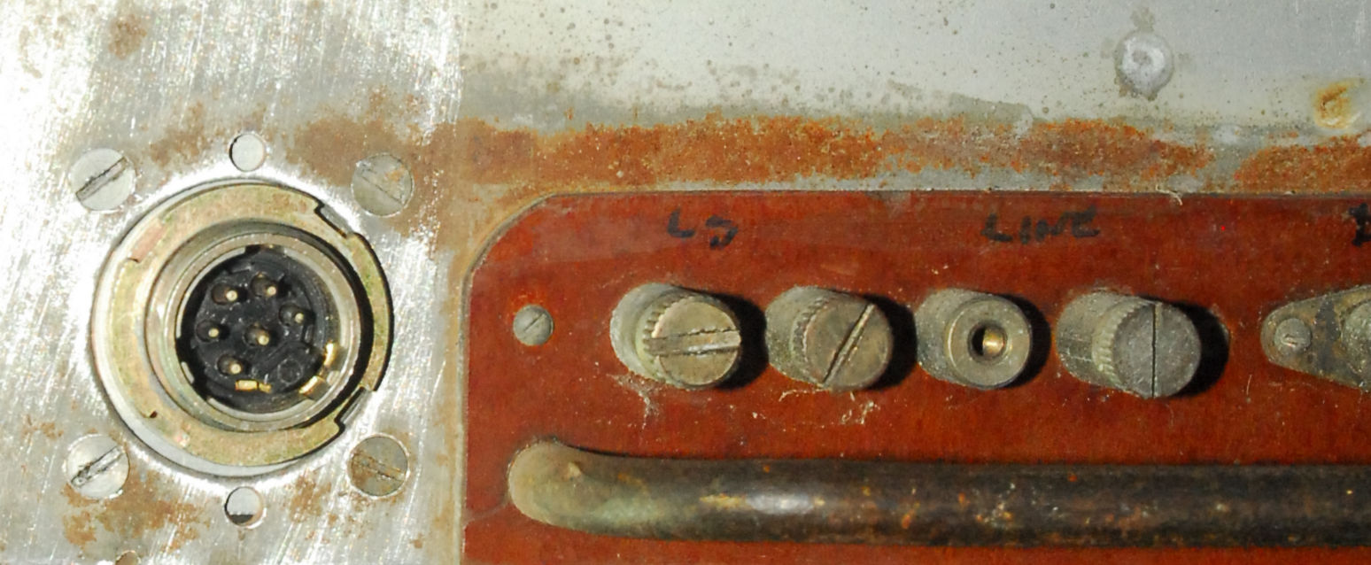
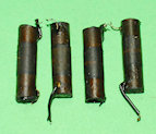
To maintain some authenticity I felt it would be worthwhile fitting a connector that would allow for both AC and DC supplies. For this I fitted a 6-way Plessey connector as used on the Racal MA259. Not up to CE standards but hey!, this is vintage kit here. I also fitted two new 10nF mains filter capacitors rated at 2KV. Next, I disembowelled the 3-way smoothing-pack, see below ... Definitely not in good condition!
6-Pin Plessey Connector
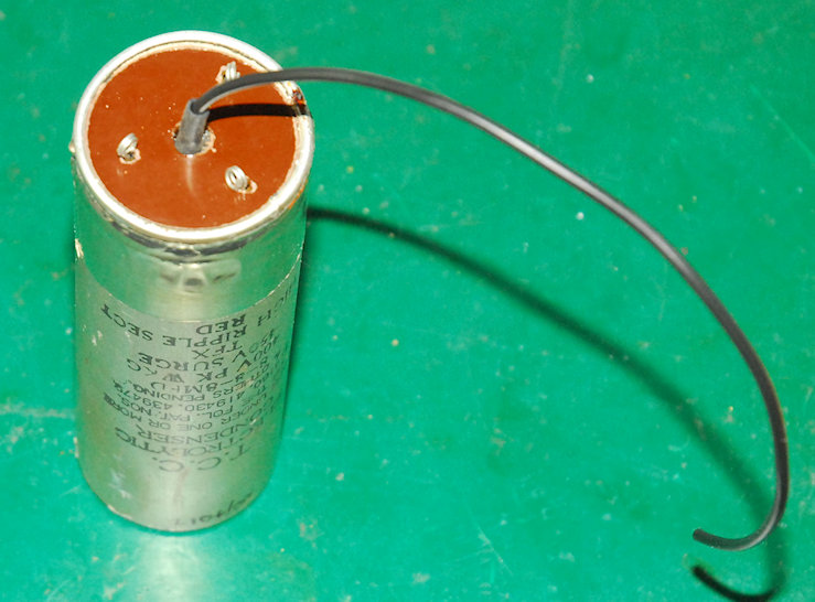
The guts of the old 8uF + 8uF + 8uF Capacitor
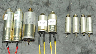
Above: Re-stuffing the 9 tubular paper capacitors in the immediate area ... The audio stages, detector/AVC and BFO circuits.
But what good is a communications receiver if the tuning mechanism is jammed?
Obviously I had to drill out the tiny rivets to remove the celluloid pieces. Re-fitting is quite simple. All I did was tap each hole in the metalwork to M3 and then very carefully counter-sink the matching holes in the celluloid. I did have to elongate the holes in the disc to compensate for shrinkage. I then cut down some small-headed counter-sunk M3 screws such that the threads did not foul on any other moving parts once the celluloid pieces we re-attached. I had to move the disc assembly very slightly, but it is all back together and the tuning mechanism action is super-smooth.
Left: Flattened celluloid pieces re-attached.
Back to the electronics ...
Left: Then I discovered this. With the larger of the two tag-boards removed from the side wall, and the two ‘phones jacks removed, I noticed a bunch of severed wires poking out from the wiring loom that runs between the front and back of the receiver. This passes through a couple of lengths of now brick-hard plastic.
Right: Another view of the six severed wires with the horrible yellow sleeving cut away. All six wires had then been cut again in the area adjacent to the rear panel terminals. The 1940s rubber insulation had perished and turned to dust. Maybe this was why they had been cut. Maybe these were the original wires between the ‘phones jacks, the audio stage (KT63) and the output transformer at the rear. If that were so, the wires were definitely cut a long time ago since the current audio wiring is definitely not new.
Above: The offending rotten wires removed. Just about to fully gut the compartment.Below: The fully refurbished compartment ... minus the metal screen.
As mentioned previously, the front panel bears a label stating that this CR100/2 was modified by Hatfield Instruments. The CR100/2 was used by the RAF primarily and to a lesser degree by the British army. RAF stores numbers can be found everywhere inside the receiver. The CR100/2 is unique in that it came with what was termed a Side-Tone Facility which the manual says can be used to mute the receiver in the presence of strong signals. The way it works is very simple. Under normal receive conditions, R57 is shorted out and the gain of the IF stages is as per that set by R41, which sets the gain by varying the level of positive bias applied to the cathodes via the 'Cathode line' in excess of the normal self bias developed across the individual cathode resitors. Use of the Side-Tone-Facility brings R57 into play each time the transmitter is keyed, effectively increasing the positive bias further and thus muting the receiver. The level of muting can be set by the operator such that they hear their own 'Side-Tone' at an appropriate level. However this one has been modified and the Side-Tone Facility has been butchered/removed. Where R57 should be, there is a small metal sub-chassis (see left) with a B7G valve socket containing a 6D2 Double-Diode. This little circuit is inserted between the triode section of V8 and the main audio stage (V9). Also, the Side-Tone Facility socket has been re-wired so that it now goes to the solenoid of what is clearly a retro-fitted Muting relay which is wired to the 'Cathode Line'. The HF-Gain control (R41) wiring does not conform to the schematic.
I was not happy with the B7G socket ... The valve was very loose, so I decided to re-build this little circuit and figure out what it did.
Right: The re-built mystery circuit on the bench undergoing test. This is a beautifully elegant and effective limiter circuit. Because the diodes are connected anode-to-anode, both top and bottom portions of the incoming waveform are clipped. The potentiometer sets the bias current and thus the voltage across the diode and thus the level of clipping. In other words the maximum level of signal into the KT63 can be limited. See the photographs below. Here I set the limiting to keep the peak-to-peak amplitude to 2V. Note how the less than 2V pk-pk sine-wave remains a sine-wave but as soon as it is increased to greater than 2V pk-pk the peaks and troughs are clipped. Obviously this will have a seriously detrimental effect on certain types of signal by adding distortion but it is an effective way of limiting the effects of strong interference.
input signal less than 2V pk-pk
input signal in excess of 2V pk-pk
Limiter circuit schematic
So what about the other wiring anomalies? I ended up doing this ...
A lot of thought has obviously gone into the construction of the CR100 such that the entire coil-box assembly can be easily removed. I had been going round in circles getting nowhere trying to figure out the wiring around R7, R39 and R40. Now I could see exactly what was going on. It looked like R40 which should be 10K, was measuring 18K and was seriously cooked too. It was also wired to the Frequency Changer coil-pack!! So it would seem. Also, it appeared that the wires to R7 and R40 had been swapped too.
Left: Coil-box removed from chassis with screen around aerial pack removed for easy access.
Below: Finally ... There be nasties in here!. On the left R7, seriously cooked. Whilst on the right, we have a partially disconnected burned-out red resistor and an ugly repair job. This is R13, the anode resistor in the RF amplifier stage.
Replacement Rs and Cs now fitted
Placement of R7, R39 and R40 in early models
Left: I believe the reason for swapping R7 and R40 was to make it easy to access the ‘far’ end of R7 which is otherwise obscured by capacitor C78 in early models. This end of R7 goes to a wire in the coil-box, and since the latter is designed to be easily removed it makes perfect sense to NOT obscure one of the solder-joints. Note the cloth-covered wire at the far end of R40. This was originally connected to R41 (HF Gain) but is now wired directly to 0V. This will be discussed later.
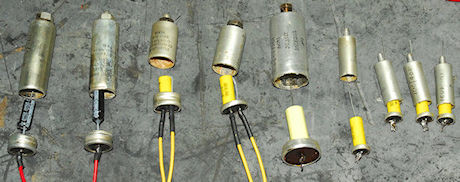
The various types of carbon resistors used
Right: The big black resistor is the original ‘cooked’ R7 which should be 20K and rated at 3W. It is so over-heated that all the paint has flaked off and it now measures 18K. I have replaced it with a modern 5W carbon 22K type. The other resistors in the photograph serve to give an idea of the different types used. Each one pictured is non-E12 series.
However, resolving the issue with R7 and R40 still left the question of the odd cloth covered wire between R40 and chassis via a pin on V4 (see above). According to the circuit diagram, that end of R40 should go to the HF (or RF) Gain control (R41) as in the diagram below.
Original hf gain wiring
Note: The junction of R39 and R40 provides the Screen Grid voltage for all the RF and IF amplifiers. Thus each time the 'Side-Tone' terminals are opened, not only does the potential on the Cathode Line increase but the Screen voltage will also increase. Is this a problem, I wonder?
Modified hf gain wiring
However, R57 is missing ... Its physical space is now taken up with the ‘Hatfield Instruments modification’. R40 no longer goes to one end of R41 and is instead now wired to 0V (Chassis), thus ensuring a constant Screen Grid voltage to the RF and IF amplifiers. The HF Gain Control is now reduced to nothing more than a variable resistor between the ‘Cathode Line’ and 0V. A 1K8 resistor has been added in parallel with R41 reducing the effective resistance to approximately 950 ohms.
A curious design feature of the CR100 is that although the mixer stage employs an VR99 Triode-Hexode (aka X65 or ECH35), a valve specifically designed as a Mixer/Oscillator ... Only the Hexode part of the valve is used (as the mixer). The Triode section, normally employed as the Local Oscillator is not used. Instead a KTW61 (or VR100) forms the Local Oscillator. The manual says that this valve is operated as a Triode, but in actual fact the configuration is more akin to that of a Tetrode since the Screen and Suppressor Grids are ‘tied’ together and connected to the Anode. There is no explanation in the manual as to why a separate valve is used for the oscillator but it may be a way of attaining a higher level and possibly more stable Local Oscillator signal whilst at the same time minimising any unwanted mixing products.
The RF, Mixer and Oscillator stages prior to refurbishment.
So, having finally figured out what was going on with R7, R39 and R40, we could then proceed with the refurbishment of the RF and IF stages.
RF Amplifiers, Mixer and Local Oscillator after refurbishment.
The IF Transformers are relatively easy to re-wire since the wires attach to solder-tags in a convenient recess space on the underside. The enclosures are tin-plate and thus soft and prone to damage (see later). The one pictured on the left is the 1st IF Transformer.
The photograph on the right shows how I use a simple pipe-cutter to open the tubular stud-mounting capacitors.
And on the left, here we have the final batch of 14 stud-mounted 100nF capacitors, re-stuffed with 630V polypropylene capacitors, awaiting refitting in the final part of the CR100 ... around V5, V6 and V7.
Muting relay.
Right: The new resistors and re-stuffed capacitors in place. But what to do about that relay and the little tag-strip? Actually I am not convinced that his was added by Hatfield Instruments. The tag-strip used for the potential divider is identical to that used in the limiter circuit but the insulation used to sleeve the joint between the green and blue wires has definitely been culled from a length of coax ... Inventive but not exactly professional. However I decided to keep the circuit since, on paper, it appears to be a clever muting circuit. The schematic is shown below.
Muting relay Schematic.
How it works: The potential divider provides a nominal +25V level. The relay actuator coil is connected across the Side Tone Facility terminals ... 12V appears to be sufficient to operate it. When not energised, all four cathode resistors are connected to the ‘Cathode Line’. When the relay is energised, resistors R36 and R37 are instead connected to the +25V from the potential divider ... Effectively turning V5 and V6 off and thus muting the receiver.
Below: All the wiring associated with the valves is now complete. The Mute relay was previously attached to the rear wall of the chassis by one of the self-tapping screws that secured the cabinet to the chassis. To me this was another reason for discounting this as part of the Hatfield Instruments mod since there are two 6BA tapped holes provided on the relay. I drilled two counter-sunk holes in the chassis and mounted the relay as per the photograph. Now when the cabinet is removed, the relay does not fall inside!
All RF and IF stages complete.
Left: The modified HF Gain control and the Level Control for the Limiter, where ALL four of the shaft screws are long cheese-head 4BA types. The ones at the front come dangerously close to the large rotating logging-scale disc. Also, the hole in the front panel for this control was so misaligned that the shaft actually came out at 45 degrees!! This accounted for the gross malformation of the shaft coupler. Such flexible couplers are intended to compensate for minor misalignments, but this was ridiculous! Luckily, I had a brand new identical coupler with appropriate grub-screws and rather fittingly, an RAF stores number.
I then drilled the front panel hole out to the same size as the other clearance holes and filed it into an oval so that the shaft came out perpendicular to the panel. I then sleeved it with a short length of neoprene before pouring epoxy resin into the excess space on the left (having covered over the rear of the space with tape). The shaft now has the same feel to it as the other front panel controls, i.e. no uncomfortable wobble.
The finished CR100/2.
So it was now time to perform a 'controlled power up'. For this I planned to remove the rectifier valve and apply HT and LT from my variable HT supply that I use when testing RA17 VFOs. This would allow me to avoid nasty surprises. But first I went through all the resistance checks listed in the manual. Confident that there were no short circuits, HT+ and Heater volts were applied and slowly wound up to 250V. Apart from what turned out to be little more than dirty contacts on the Operation Switch, the CR100 worked first time. On the whole, frequency accuracy wasn't bad with the exception of Band 6 where everything was slightly to the 'right'.
Running through the alignment procedure for the coil-box, I found an error in the manual. In figure 22 on page 55, tuned inductors H.F.3 and H.F.4 are swapped. Everything peaked up nicely although the frequency accuracy at the top end of each band is a little bit out. The Local Oscillator was a tad stubborn to start on Band 4 ... another dirty contact issue, so the can of De-Oxit came out again. As I was rocking the band-switch back and forth the drive-cord for the drum came off! Unlike the cord for the pointer, the one for the drum was more like parcel-string! This is quite aparent in a couple of previous photographs relating the the HF Gain and Limiter controls. Fortunately I have a roll of proper drive-cord. The manual has some excellent instructions for re-stringing the two drive-cords and it was here that I learned that this CR100/2 may not be as early as first thought, as it has the later 5-pulley system for rotating the drum. Re-stringing the drum cord is not something that can be rushed and an extra pair of hands does help.
The photograph on the left shows the new drum drive-cord.
I took a small length (5cm) of 0.7mm steel wire and folded it in half such that the radius of the bend was about 1.5mm. I then placed it over the cord to the right of the pointer as in the photograph on the right. I then folded the ends over so as to complete the circle, as it were, and turned the loop such that it put a single twist in the cord. This was sufficient to take up the slack completely. One end of the wire was tied to the cord with a small cable-tie whilst the other was simply cut off. The stiffness of the wire allows for this. Copper wire would probably be too soft and un-wind. The slack is now gone. There is no longer any 'lag' when tuning, which is still silky-smooth. Job done!
I was not really too sure about the bandwidth settings ... there being little difference between 1.2KHz and 3KHz for instance. There's a whole raft of instructions in the manual regards performing the IF alignment which makes fascinating reading. Clearly Marconi were writing the book on receiver alignment based on their own in-house test equipment and some Cossor kit. What on earth is a ganging oscillator? I on the other hand have a network analyser. The only problem is that it is a 50-ohm instrument and care must be taken to NOT load (and de-tune) the circuits that you are attempting to align.
I eventually adapted a method that I use for 'shaping' the IF bandwidths in the RA17 series. I removed V4, the Local Oscillator and injected the sweep oscillator via 100nF to V3 pin 3. The analyser input was connected to the top-cap of V7, again via 100nF. Ideally I would have liked to connect it to the input of the detector but the metal screen around the detector circuitry was in place and since it is a real pain to fit I was NOT keen to remove it. So the alignment was going to be slightly compromised.
Unlike the RA17 series, the Bandwidths in the CR100 are a mix of IF and AF. The lowest 'real' IF bandwidth is actually 1.2KHz with 100Hz (and maybe 300Hz) being audio filters. I say maybe because I have not been able to find anything in the manual which specifically refers to the 300Hz position. According to the manual, IF alignment is carried out at 1.2KHz, which brings the crystal into play. Once you have identified the crystal 'response', IF1 and IF2 and adjusted to maximise the crystal 'response' whilst minimising any other response. This was easy to perform using my network analyser (as a wobbulator). There after, all other IF tansformers can be adjusted to maximise the crystal 'response'. (IF5 was later adjusted for maximum sensitivity). The manual is most clear that no adjustments should be made with the bandwidth set to 300Hz.
With the analyser disconnected and V4 re-fitted, the IF bandwidths all sound good with the exception of 300Hz, which sounds almost as wide as the 1.2KHz setting. The 100Hz audio filter is beautifully sharp. Looking at the circuit diagram, when 100Hz B/W is selected, S15 selects the Hi-Q band-pass filter formed by L62 and L63 etc. However, when the 300Hz B/W is selected, the filter is by-passed altogether. This would explain why there is negligible difference between the 300Hz and 1.2KHz bandwidths. ALSO ... remember that the Hatfield Instruments Pulse limiter is permanently connected between the output of the filter (S15 pin 5) and the audio output stage. The nature of this circuit must to a certain degree have an effect on the frequency response, albeit High-Pass in nature.
Connected to a high quality loudspeaker, the CR100 is surprising good on AM and CW. With judicious use of the HF Gain and BFO controls SSB doesn't sound too bad. With all its Rs and Cs replaced with modern types, the overall sensitivity is comparable with the RA17, with 20dB signal-to-noise being easily achieved for 1uV at the aerial input. The CR100 in general is said to be prone to VFO drift. However this one was remarkably stable with only a noticeable drift within the first 30 minutes from switch-on. If only my CR300 had performed as well as this!
Next post in the series: Refurbishing a Marconi CR100/1