Racal MA251 Buffer Amplifier
4 minute read
September 2015
When an RA.66 Panoramic Display is used in conjunction with either an RA.17 or RA.17L it is first necessary to fit an MA.251 Buffer Amplifier between the receiver’s 2nd and 3rd mixer stages. RA.66s are very rare and sought after. MA.251s are even rarer.
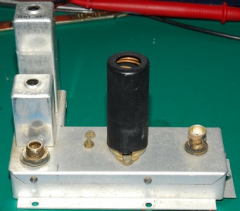
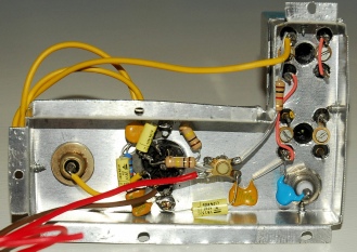
Genuine MA.251 from RA17L N3372. Note: The BNC and Pye connectors are swapped.
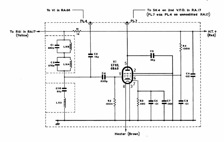
MA251 Schematic
About a year ago, a friend of mine who has two RA.66s (one already partnered with an RA.17L) asked me to look into making a second MA.251 so that he could connect his other RA.66 to a second RA17. As I suspected, getting my hands on an ‘spare’ MA.251 was out of the question. I suspect that most working RA.66s are permanently partnered with an MA.251-equipped receiver. Or, to put it another way; If someone has an MA.251-equipped RA17, they more than likely also have an RA66. Therefore, given the certain non-availability of a genuine MA.251, the alternative is to construct one from scratch.
Since starting this little project, I have obtained two detailed diagrams for making the sub-chassis from aluminium sheet. Both are for making a one-piece chassis. I looked at this design and concluded that although it looked simple enough, without specialist bending jigs, I would have a problem with some of the bends. Consequently I opted for a two-part (walls and lid) affair as in the original. The walls are simply a long strip of aluminium carefully bent into shape and then tabs bent over for the mounting screws. The matching lid was then made to fit over the walls. Again, the edges were folded over (as in the original) and self-tapping screws used to secure it in place.
Since starting this little project, I have obtained two detailed diagrams for making the sub-chassis from aluminium sheet. Both are for making a one-piece chassis. I looked at this design and concluded that although it looked simple enough, without specialist bending jigs, I would have a problem with some of the bends. Consequently I opted for a two-part (walls and lid) affair as in the original. The walls are simply a long strip of aluminium carefully bent into shape and then tabs bent over for the mounting screws. The matching lid was then made to fit over the walls. Again, the edges were folded over (as in the original) and self-tapping screws used to secure it in place.
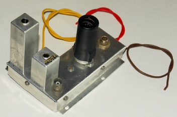
Two views of the completed MA.251 ‘clone’. Note how the BNC and Pye connectors are swapped. (See photograph above).
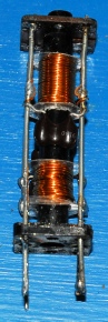
With the exception of Coil Assembly L51A/L51B, all components required to make the MA.251 are either on the host RA17 or easily obtainable. L52 and the Pye connector can be taken from the sub-chassis that is removed from the receiver as part of the installation procedure. This redundant sub-chassis can then be used as a template for the holes to be drilled in the MA.251 lid. L52 and the connector can then be mounted as before. However L51A and L51B posed a bit of a problem. The can is the larger 63mm version, so the original L51 assembly cannot be re-cycled. But even with the correct size former and can, I still did not know the value or winding details. L51A and L51B are high-Z traps and I originally thought they were to reduce sprurii at 1MHz and 2MHz. I am indebted yet again to Brain Goldsmith in Australia who very kindly sent me some annotated drawings identifying L51A and L51B; giving their resonant frequencies as 3MHz and 2MHz respectively. The annotations also included the winding details! Cheers Brian!
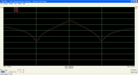
Frequency response of L51A/L51B. Span 1.5MHz - 3.5MHz, centred on 2.5MHz
L51A is 34 turns of 26 B&S gauge, 2 layers. L51B is 48 turns of 26 B&S gauge, 2 layers. I had never come across B&S gauge wire before, but apparently swg 27 is very close. Unfortunately I didn’t have any. However I did have a large spool of swg 26 enamelled copper wire and decided to give that a go. I used round mica washers with their centres drilled out to 8mm to keep the windings in place. The use of different gauge wire was proved inconsequential initially, although on fitting the can, the resonant frequency of L51B shifted HF and I had to change C1 from 330pF to 390pF to bring the frequency within the range of adjustment.
The instructions for installing the MA.251 are in the RA.66 manual so I won’t discuss them in detail. This manual can be downloaded free from BAMA and contains a few additions; one being a hand drawn but detailed sketch of how to make your own MA.251 chassis. In addition, there is also a photograph that someone has added of an MA.251 installed in an RA17.
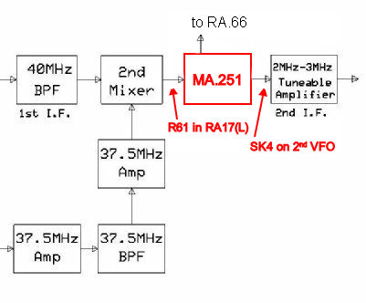
I have an idea which may explain why the BNC and Pye connectors were swapped in the MA.251 that was fitted in RA17L N3372. The MA.251 is a buffer amplifier designed to isolate the RA17 from any loading as a result of connection to an RA.66. The EF93 stage feeds the 3rd mixer in the RA17, NOT the RA.66, as I suspect some people have wrongly assumed … and may be the reason behind the afore mentioned anomalies … see the diagram below.
I have an idea which may explain why the BNC and Pye connectors were swapped in the MA.251 that was fitted in RA17L N3372. The MA.251 is a buffer amplifier designed to isolate the RA17 from any loading as a result of connection to an RA.66. The EF93 stage feeds the 3rd mixer in the RA17, NOT the RA.66, as I suspect some people have wrongly assumed … and may be the reason behind the afore mentioned anomalies … see the diagram below.
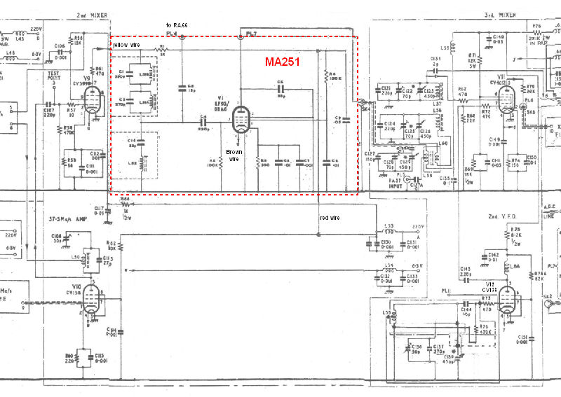
Partial RA17L schematic with MA251 installed