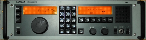
The Racal RA1792
23 minute read
September 2016
Racal's first microprosseor-controlled radio
Although I cannot claim to be an expert on the 1792, having recently rebuilt five working specimens from several crates of boards, I felt I should write a ‘piece’ on the type.
I once saw an Ebay auction where the seller described the item as an example of the ‘Legendary’ RA1792. To me, being the owner of an RA1792, that description sounded a bit over the top.
I think perhaps two Racal HF receivers do qualify for being described as legendary. These being the RA17 and the RA1772 … the latter for its sheer outstanding performance and the former for its ground breaking technology and the fact that it put Racal on the map regards HF communications. If there is anything for which the 1792 might be described legendary it would be its propensity for popping its tantalum bead capacitors … blue ones especially!
The 1792 came after the 177x series and was a direct response to a US government requirement for a low cost HF communications receiver with the minimum of front panel controls. The 177x might have fulfilled this requirement had it not been so expensive to manufacture.
Although some aspects of the 177x, such as the first and second mixers were more or less carried forward in the design, the 1792 was a completely new receiver. Designed in the US at Racal’s site in Rockville, Maryland, the RA1792 became Racal’s first microprocessor-controlled receiver. It was also their first receiver to employ large custom-made LCD displays. Both of these features have since been the source of several issues that have essentially plagued the type. And then there’s the well know issue surrounding Racal’s choice of blue tantalum bead capacitors.
Perhaps the most common issue to blight the 1792 is the bleeding that can occur within the LCD modules. The extent of this can range from small aberrations which are little more than a cosmetic annoyance, to a completely unreadable display. The cause of this is largely down to the manufacturing process (such large custom displays were very rare in the early 1980s) and the environment that the receiver is used or stored in. Racal also made the decision to ‘single-source’ the display modules … not necessarily a good idea, but remember these were state-of-the art custom units.
Most processor boards have issues with corrosion around the via-holes resulting in continuity issues. Admittedly this is a manufacturing process issue. The first batteries used for on-board backup tended to leak, resulting in severe corrosion to the extent that the board would need to be scrapped. Then there is the choice of processor, the Fairchild F8 or 3850 which became obsolete while the RA1792 was still in production, thus the cost of spares became extortionate.
Performance of the RA1792 can be described as adequate in that it in no way comes close to that of its predecessor, the 1778. However it is a joy to use and everything you need to know at any time is provided on the two LCD displays.
The Pre-Amp/LP Filter
One failing of the RA1792 is its lack of input preselector and its tendency to react badly to very strong signals. However it does come with a low-pass filter.
Right …
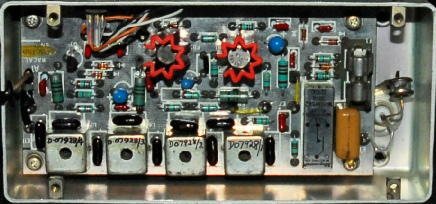
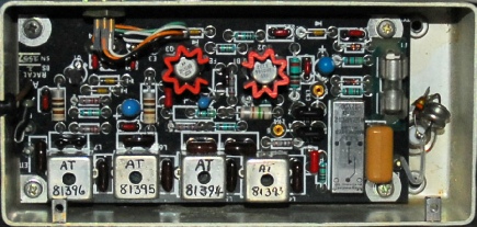
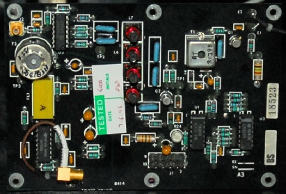
Two incarnations of the receive pre-amp/low-pass filter unit. The one at the top is an ‘older’ version where the links for bypassing the amplifier are wires as opposed to plug-in links as in the later version below. There are also a few subtle component placement changes.
Whether active or not, this unit does afford the receiver a great deal of protection in that it contains both a fuse and a spark gap. The input can withstand a sustained e.m.f of 50V.
Gain of the unit (Incl. filter) is approximately 10dB.
Perhaps the fact that the active stage can be bypassed is an admission that the first mixer can be overloaded.
The First Mixer
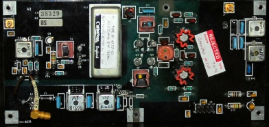
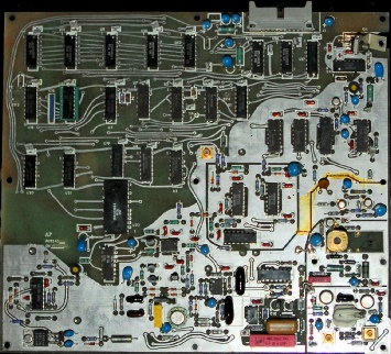
To date I have encountered two versions of the 1st mixer board. The silk-screen on the one on the left indicates that early versions of this board carried additional circuitry; possibly a pre-mixer amplification stage. The 1st mixer board converts the input RF signal to the 1st IF of 40.455MHz. The LO signal from the 1st LO synthesiser is LP-filtered before being fed to the FET Switching Mixer by the balanced drive amplifier. The RF input signal is passed to the input of the mixer by another LP-filter. The resulting output is then fed through a 40.455MHz roofing-filter which has a 3dB bandwidth of 16KHz. The output of the filter is then amplified by a single grounded-gate FET amplifier whose gain is controlled via AGC.
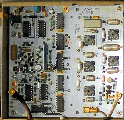
The 1st LO Synthesiser
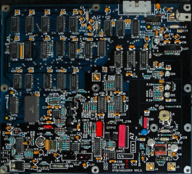
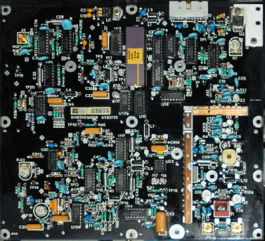
I am not even going to try to describe the operation of the 1st LO synthesiser other than to say that ultimately there are two distinct versions; MK3 & MK4 … the latter of which is based around an LSI chip (the one with the gold top). In both cases the reference frequency comes from the 2nd LO synthesiser board … 1MHz for the MK3, 20MHz for the MK4. The LO o/p is between 40.605MHz and 70.445MHz.
Above, we have two other 1st LO boards. One of these works if it is addressed as a MK3. The other is faulty. The differences between the two are minimal. It is possible that these are essentially MK2s, although I have no proof.
The 2nd LO Synthesiser
Old Style
New Style
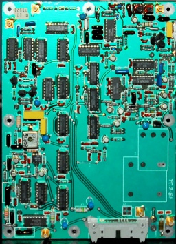
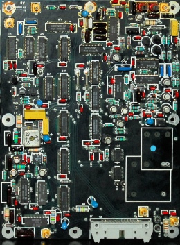
Just as there are two possible versions of 1st LO, there are also two possible versions of 2nd LO. The newer version includes a pair of extra buffer amplifiers and a couple of extra test points. The 2nd LO board, as well as providing the reference frequency for the 1st LO, gets its own reference from one of three possible sources. The most common frequency source being an off-board but local 5MHz ovenised oscillator (see below). Alternatively there is provision for a local on-board 5MHz reference or an external source which can be either 1MHz, 5MHz or 10MHz. The two wire links in the centre of the board are used to select the input frequency of this external source. Since the 2nd IF in the RA1792 is 455KHz, the 2nd LO output is 40MHz. The 2nd LO synthesiser board also incorporates the BFO circuitry, the output of which is centred on 455KHz.
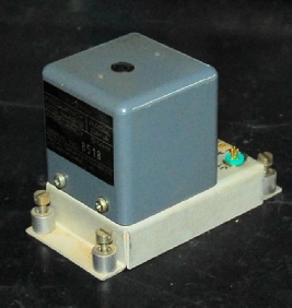
Racal-Dana ovenised 5MHz Frequency Standard type 9442/12
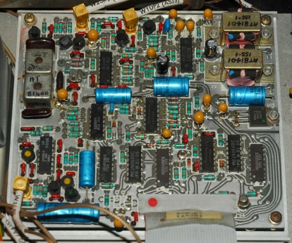
The 2nd Mixer
There is more to this little board than initially meets the eye. Q1 and Q2 form a two-stage tuned amplifier at 40.455MHz, the gain of which is AGC controlled by U1, U2 and PIN Diode CR1. The output is then fed through a band-pass filter at 40.455MHz on the input to U3 (MC1496P), which is configured as a double-balanced mixer. The resulting 455KHz output is selected by the tuned transformer T2 and ceramic band-pass filter FL1 before final amplification by U4. This signal is then fed to the main IF/Filter board.
The PSU
If there is one thing to really love about the RA1792 it has to be the Power Supply. Nothing complex here. Just a simple linear PSU using TO-3-style regulators. Not a switcher in sight … unlike the PSU in the RA1795 which is pure evil!
Actually, in hind sight, there is one awkward feature of this PSU and that is the inclusion of two wire links which act as fuses. These are on the outputs of what is termed the +5V (unreg) and +15V (Audio) … both of which come from the input of the respective regulators … i.e. the unregulated inputs. Given the 1792’s appetite for ‘blue tants’, at least one of these wire fuses is guaranteed to blow during the life of an un-refurbished receiver. Replacing the wire fuse is physically simple but who do you know carries exactly the correct gauge of wire for the job? All I do is take a length of 36 strand wire, remove one strand and re-wire the fuse with that.
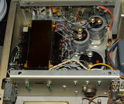
The photograph on the right is the PSU in my own RA1792. Note the two resistors mounted on insulated stand-offs on the outside of the box. These are in series with the AC feed to the back-lights. My 1792 was originally a non-back-lit model. However when I got it, both the displays were unreadable and when I obtained a replacement front panel assembly it turned out to be back-lit. Modifying the PSU is very simple. Refer to the schematic in the service manual for actual details.
The photograph on the right is the PSU in my own RA1792. Note the two resistors mounted on insulated stand-offs on the outside of the box. These are in series with the AC feed to the back-lights. My 1792 was originally a non-back-lit model. However when I got it, both the displays were unreadable and when I obtained a replacement front panel assembly it turned out to be back-lit. Modifying the PSU is very simple. Refer to the schematic in the service manual for actual details.
The A4 Board
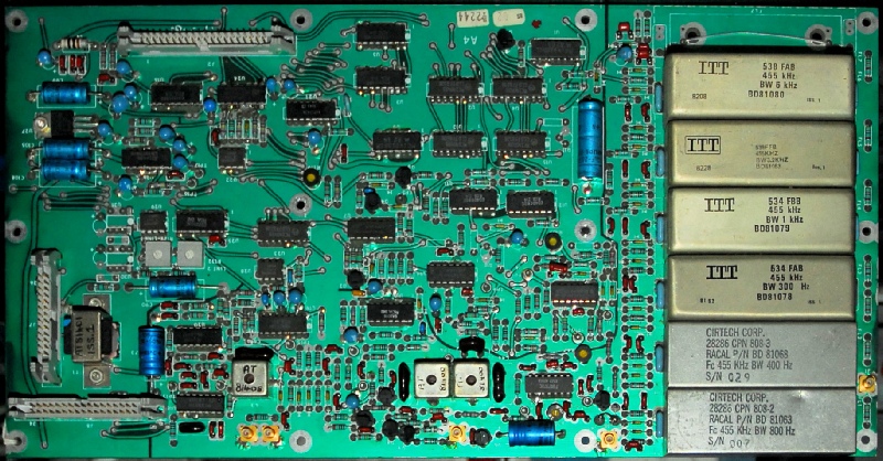
This is the final board in the RF path. Although its official name is Main IF/AF, this board does a lot more. It carries the selectable IF filters, the 2nd IF amplifier, Product Detector, FM Detector, AGC detector and distribution, AF amplification, AF & RF ‘meter’ driver and D/A … plus a host of solid-state switching. Hence why it is easier to refer to it by its other designation … A4.
The board in the above photograph is not the final build standard. Note the two unpopulated IC locations on the left. These don’t feature on later boards. There are 27 different filter configurations that I am aware of. The configuration pictured above is applicable to Suffix GP and was peculiar to ‘Piccolo’ systems. Note the bottom two filters: the USB filter is 400Hz and the LSB filter is 800Hz. If there are any configurations that can be considered ‘general purpose’ then these would be suffixes GA and GB.
The basic filter settings are 16KHz, 6KHz, 3KHz, 1KHz and 300Hz. The 16KHz setting bypasses the filters on the A4 board and relies solely on the Roofing Filter on the 1st Mixer board. The remaining 4 bandwidths are set by the filters on the A4 board. However the GA and GB configurations differ in the way the 3KHz bandwidth is created. Receivers with suffix GB carry a full set of symmetrical filters for 300Hz through 6KHz, whereas receivers with suffix GA carry one less; there is no symmetrical 3KHz filter. Instead the 3KHz bandwidth is derived by selecting the USB filter (2.7KHz or 3.2KHz) and offsetting the 1st LO and BFO by 1.7KHz. I have found USB & LSB filters of 2.7KHz and 3.2KHz B/W. The bandwidth displayed in the RH display appears to be determined by the firmware. My own Suffix GA 1792 has 2.7KHz filters, yet the B/W is displayed as 3KHz. One of the 1792s that I have just rebuilt has 3.2KHz filters fitted and the display indicates 3.2KHz when BW3 is selected. I had to make sure that I didn’t fit 2.7KHz filters in that receiver! There may be other configurations that also employ a derived BW3 setting.
Essentially the RA1792 is a very straight-forward receiver and that is definitely true when it comes down to what it does. It is even easy to test, manually. However the majority of RA1792s come with BITE: That is Built In Test Equipment. Being ex-Racal myself, the concept of BITE is not alien. However, the BITE in the RA1792 can be both your best friend AND your worst nightmare!
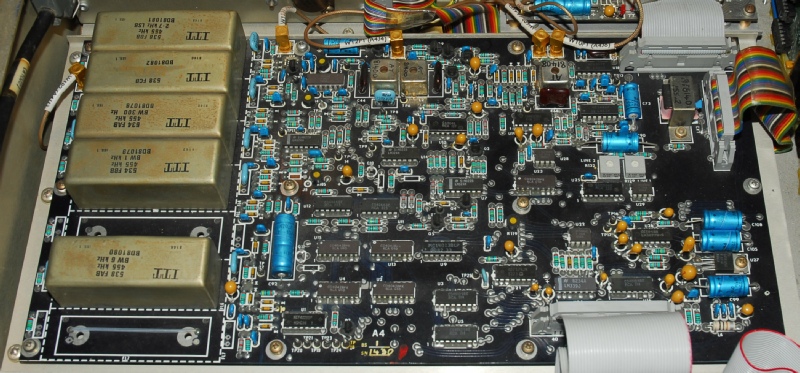 The A4 board (with derived BW3) in my RA1792
Basically it is possible to have an RA1792 that for all intents and purposes is working perfectly … as a radio, but yet fails the BITE in more that one place. There are two ‘layers’ of BITE … continuous and user-invoked. Certain BITE functions are monitored continuously, some at ‘switch on’ and others come into play when invoked by the user. For instance the various supply voltages throughout the receiver are checked at switch on … and if one is out of spec. the dreaded ‘fault’ flag appears in the RH display. Cleverly, the extent of BITE is dependent on the options fitted. BITE can be invoked by pressing and holding the REM key, keying in 00 then releasing REM. If BITE encounters a fault the sequence is halted and the failed test number is displayed in the LH display. BITE can be invoked to start at any applicable test simply by keying in that particular number whilst holding in the REM key. How does this impinge on the A4 board? Well, it’s all about the DAC which is located on the A4 board. When the BITE is checking voltage levels, the output of the DAC is used as the reference. On the odd occasion it is possible to have the DAC set within limits and still find yourself going round in circles trying to find a fault in a seemingly fully working radio, only to find that a minuscule tweak of the DAC clears the fault. Another ‘fault’ which stalled my work for some time was a BITE failure relating to the 1st LO. In this case the board was a MK3 and the RX was working perfectly. The failed test implied that the varactor voltage was out of spec. It very definitely was NOT and the relevant paragraph in the service manual was about as useful as a chocolate tea-pot!! I eventually tracked the problem down to a wrong value resistor on the LO board. This was a part of the board which was dedicated to the BITE, hence why the RX was working fine. Not only that, but I found another two MK3 LO boards with the same anomaly. The 4th board that I looked at complied with the schematic. I replaced the errant 1K resistor with a 22K as per the schematic and the RX sailed through the entire BITE sequence without a single failure. It is possible that changing the 22K for 1K was for a pre-BITE system or for a board setting known as ‘Quick-Lock’ … but I can’t be sure.
The Front Panel Assembly
The front panel assembly encompasses the Switch & Display Board and the Front Panel Memory Board (FPM). Both come in at least two flavours. Oddly it would appear that Racal only fitted back-lit LCD displays to the Mark 6 receiver. This required fitting a network of 16 light-bulbs behind each display. This in turn requires two additional pcb tracks on the FPM board.
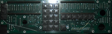
The photographs above show a basic non-back-lit display board. The displays and switches are mounted on the front with the ICs mounted on the rear. All push buttons (keys) are magnetic reed relay type.
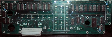
The photographs on the right show two clearly different types of FPM board … the (earlier) light green version is clearly not as wide. This is because this is a pre-BITE FPM board. U31 and U32 do not feature on pre-BITE FPMs.
The FPM board, as its name suggests, is in part a memory board. Two EAROM chips, U13 & U14 (ER3400) retain such information as mode settings as input via the front panel keys. Also included on this board is the circuitry associated with the optical shaft encoder and in the case of the board in the bottom photograph, the BITE monitoring multiplexor, U31 and U32.
Finally, the FPM board serves to distribute all non-RF pathways throughout the receiver
The Processor Board
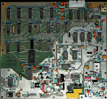
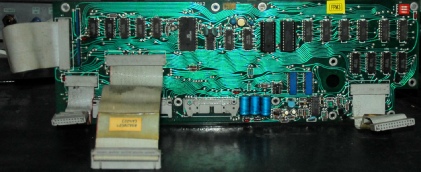
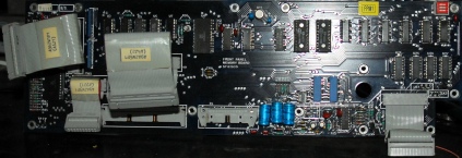
It goes without saying that the history of the Processor Board is colourful. Note the four different styles pictured below … and I wouldn’t rule out there being others out there.
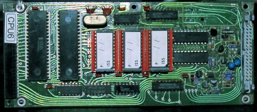
Early pre-BITE, 3 x EPROM, 2 x RAM, old-style battery, 1982?
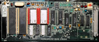
2 x EPROM, 2 x RAM, new-style battery, 1989?
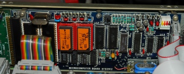
The Processor board in my RA1792 Same as ‘top right’ but with new battery on daughter board. Firmware appears to be ‘special’ X82121
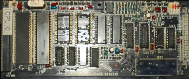
2 x EPROM, 2 x RAM, old-style battery, 1988?
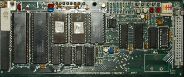
2 x EPROM, 1 x RAM, new-style battery, 1989?
The chosen microprocessor for the RA1792 was the Fairchild F8 or 3850 and like most processors of its time, additional interface chips were required. Thus a 3853 Static Memory Interface (SMI) chip is mounted alongside. Depending on board version, the firmware is located on either 3 x 2716 or 2 x 2532 EPROMs with either 1 x TC5517 or 2 x D445LC as non-volatile RAM. CPU clock speed is an eye-watering 2MHz!
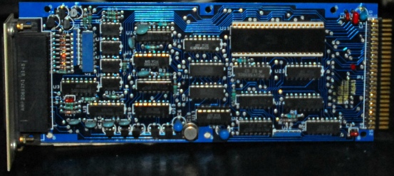
ISB and 100KHz Options
Probably the most common ‘option’ to be found in an RA1792 is the Independent Sideband (ISB) board pictured on the right. The input circuitry on this board is identical to that on the A4 board.
From the manual: Selection of the position of LK1 on the Main IF/AF board allows filter FL1 (LSB) to be connected to the ISB IF/AF board, whilst leaving the other filters connected to the main circuitry. For modes other than ISB, only one filter is selected. When the ISB option is used, however, two filters are selected under software control, FL1 for LSB and FL2 for USB
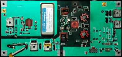
The photograph on the left is of the 100KHz IF option board. This is mounted within a screened box which sits where the ISB board would normally fit. This essentially provides a third IF of 100KHz. The manual states that this replaces the 455KHz IF. This is ONLY true with respect the Main IF output at J2 on the 1792 rear panel. Even with the 100KHz option installed, the main A4 board in the RX is still responsible for the IF filter bandwidths and what comes out as resolved audio.
The option manual is also a bit misleading in that the installation guide assumes that the 1st LO in the RX is a MK3 board which takes its 1MHz reference from the 2nd LO board. In which case, since the 100KHz board also requires a 1MHz reference, the 1MHz from the 2nd LO is first routed to the 100KHz board then on to the MK3 1st LO. This is unnecessary when the 1st LO is a MK4 (reference is 20MHz). In this case no connection is required to J3 on the 100KHz board, as in the photograph on the left. This board allows the RA1792 to be connected to various legacy auxiliary units whose input is 100KHz.
Optional External Interfaces
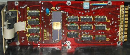
SCORE Card
Software Control Of Racal Equipment
This card allows the receiver to be controlled remotely by the MA1075 Controller. It also allows two receivers to be linked for space diversity operation.
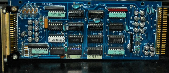
Channel Interface Board
This card provides for extended control of 100-channel selection with revertive indication and band-search or clarifier operation in conjunction with units such as the MA1100 Operator Terminal Unit or the MA1107 Automatic Search Unit.
Industry standard
IEEE-488 (GPIB) Interface
Final thoughts and links to useful pages
My own RA1792 was left over from a propagation experiment that Racal started (I think) in the mid 1980s. To cut a long story short, it and the accompanying 1723 drive unit were ‘stored’ in an environment which exposed them to extremes of temperature … cold in the winter and hot in the summer. This ultimately destroyed the LCD displays in both cases. So when I ‘inherited’ the kit, both were in a sorry state. The 1792 performed well as a receiver but I could never get the 1723 to do anything, so I parted company with it some time ago.
The issue with the ‘bleeding’ displays was resolved by replacing the entire front panel assembly and the PSU was modified to support the back-lit displays. Ultimately I replaced all the tantalum bead capacitors with new ones. It had a tendency to make loud crackles when switched on, accompanied with an ominous flickering of the back-lights! Rather worryingly, changing the tants didn’t resolve this issue, and everyone who I mentioned this to said the same thing … “it’ll be a tant about to pop” … and I tended to agree too. However, I had many other radios to attend to, having started my RA17 restoration service, so the flickering back-light problem was put on the ‘back burner’.
Last week I finished re-building five RA1792s so I decided to tackle what was obviously a fault on my own 1792. I hooked an oscilloscope up to the +5V rail at the PSU and switched on. Huge spikes were visible for several seconds before the trace settled down to a smooth flat line. I switched off the RX and unplugged each of the ribbon cables to the individual boards in turn. Ultimately all I had was the PSU, yet the spikes were still there. So the fault was in the PSU! That was a relief. The PSU in the 1792 is about as simple as they come. Looking at the schematic there were really only two possible suspects … two axial-lead 1uF tantalum capacitors … one either side of the 5V regulator. These were replaced with aluminium types, yet the problem persisted. Then I thought “what if the fault is on the other side of the mains transformer?”. I had joked a few times that it might be a dirty mains switch! I dug out a scrap 1792 front panel complete with switch and mains cable. It was filthy! After cleaning it up, I substituted the switch and cable assembly for my own one and switched on. BINGO! No flickering back-lights, no loud crackles and no voltage spikes on the +5V rail. I didn’t leave it at that. This had been an intermittent problem, so I was taking no chances. But after several hours of operation and switching it off and on many times, the problem has gone … a dirty mains switch!!!
Although I have other receivers including an RA1772 and an RA3701 to name two, I do like the RA1792. Its 16KHz roofing filter offers the widest IF bandwidth in my collection, giving superb AM reception quality when used with an external speaker. The 1Hz tuning resolution is super smooth and switching modes and bandwidths is a breeze.
One thing that does let the type down though is the paintwork. Yes, there are lots of RA17s out there with tattered looking front panels, but some of these are pushing 60 years old! The 1792 has only been around half that time.The problem appears to be a lack of primer. I have a bunch of front panels where the grey paint is coming off in large flakes; notably where labels or stickers had been placed. Where the paint has come off there is bare metal exposed … no primer!!
Useful RA1792-related links
Keith’s vintage Racal Racal Enthusiast site has a mass of information on the RA1792.
Dave Schofield’s alternative to the infamous display problem.
Manuals and schematics at the Premium Receiver group.
Replacement Processor boards and more are still available from Phill Simmons. His website is now closed but you can contact him via email.
Finally … Replacement LCD modules for your RA1792. December 2020 ... Link appears to be dead