The RA3701 HF Receiver
10 minute read
This post is part of the series 'The Racal 3700 Series':
Next post in the series: The RA3712 Dual HF Receiver
- The RA3700 Series
- The RA3701 HF Receiver
- The RA3712 Dual HF Receiver
- The MA3752 Dual HF Drive Unit
- The RA3702 Dual HF Receiver
- The TA3762 250W Linear Amplifier
- The MA3772 1KW HF Combiner
- The MA3752 driving a TA3762 PA
June 2017
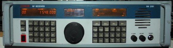
If the RA1792 was Racal’s first microprocessor-controlled HF receiver, then the RA3701 might be described as a 1792 with all the faults fixed … or so say some of the critics. That is undoubtedly harsh criticism of the earlier 1792 which was in itself both ground-breaking and relatively inexpensive to manufacture.
To describe the 3701 as a re-manufactured 1792 is not entirely accurate either. Yes, the basic architecture is essentially the same but aside from the obvious physical differences (which I will come back to), the 3701 is significantly different electronically. Whereas the 1792 uses the archaic and obsolete Fairchild F8 processor, the 3700 series employs the widely respected 68000 from Motorola. Ironically the 68000 first emerged in the early/mid 1980s when the 1792 was in production. Secondly, the 2nd IF in the 3701 is 1.4MHz as opposed to 455KHz. The most obvious improvement is in the displays. All three are essentially compound back-lit LCDs in that they all embody two forms of display. All three embody full text elements as labels. The left display is otherwise a conventional 7-segment display, the centre display is a bar-graph display and the right display is a dot-matrix alpha-numeric display. ALL three are back-lit by either two or four wire-ended filament bulbs mounted on daughter-boards which mount onto the rear of the Front Panel assembly. These are very easy to replace (something that cannot be said for the back-light bulbs in the 1792!) Under certain circumstances, these bulbs can frequently blow and some people have attempted to replace them with more reliable LEDs. However, as far as I can ascertain, no-one has yet been successful. The reason being that the 3700 series employs a fiendishly complex PWM system for powering the bulbs and controlling their brightness. Simply replacing them with LEDs is never going to work.
Mechanically, the 3701 is a huge improvement on the 1792; most notably is the fact that it is modular. All the modules with the exception of the PSU and front panel, are connected via the common back-plane. Another difference, probably not too apparent, is that not only is the front panel four times thicker than that of the 1792, it is also properly painted. Many 1792 front panels have large areas of exposed bare metal. This is because of the lack of primer (to save money?). Consequently, stick-on labels were prone to lifting off the paint when removed. If there is a down-side to the 3701’s mechanical architecture, then that would be the modular nature, which has already been hailed as an improvement. The modular nature allows the receiver to be easily configured to the customer’s requirements and does to an extent reduce the level of extraneous noise pick-up. However, with each module being individually encased in its own aluminium box with either milled or sheet covers, and the fact that they are literally touching each other, there is no way to access the module electronics without a custom extender kit. I ended up making a flexible extender cable … 64 wires, 128 solder joints and an inordinate amount of heat-shrink insulation!
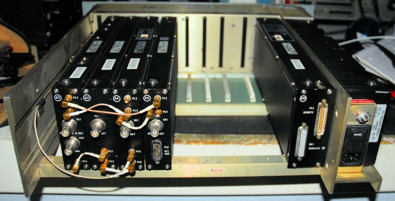
The photograph above shows a ‘basic configuration’ RA3701, as viewed from the rear. The unit on the far-right with the Earth-stud and IEC connector is the PSU Module (part of). The rest of the PSU is actually housed in the chassis behind the Front Panel. Of the five plug-in modules, the one on its own on the right, is the Processor (module A10). This actually comes in two flavours: Remote control via Serial ASCII RS423-A (pictured) or GPIB.
Moving over to the left side the fitted modules are:
A2: RF Front End Module type ST86486
A3: 1st LO Synthesiser Module type ST86487
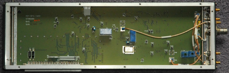
A4: Ref/BFO Module type ST86488
A5: IF/AF Module type ST86484
Moving over to the left side the fitted modules are:
A2: RF Front End Module type ST86486
A3: 1st LO Synthesiser Module type ST86487
A4: Ref/BFO Module type ST86488
A5: IF/AF Module type ST86484
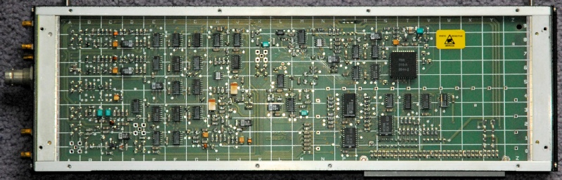
Processor Module
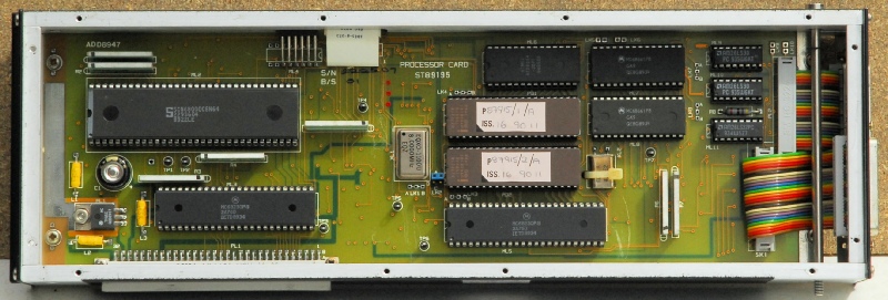
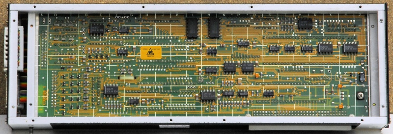
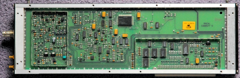
These two photographs show the inside of the 3700-series Processor Module. The drawing number varies depending on the end-product. The firmware stored in the two 64Kx16 EPROMs is also dependent on the end-product and since the firmware version in the photograph is P87915 issue 16, this is actually the Processor Module from an RA3712. Note the extensive use of surface-mounted components on the underside of the board. Note also that all the ICs on the top-side are ‘socketed’
Whereas the processor board in the 1792 employed a battery, which invariably leaked, the volatile RAM in the 3700-series processor module is maintained by the 0.47F Super Capacitor … the round device, bottom-left in the top photograph.
Firmware versions (Known, as of July 2017):
P87915/12 … For 3701 with FSK Module. Ignores presence of Sub Octave Filter Module.
P87925/14 … For 3701 … only version that I know of which supports the Sub-Octave Filter Module.
P87915/16 … For 3712
P87915/18 … For 3712
P87915/20 … For 3701 … Supports ‘changing tuning rate widely’ (sic.)
P87915/23 … For 3701
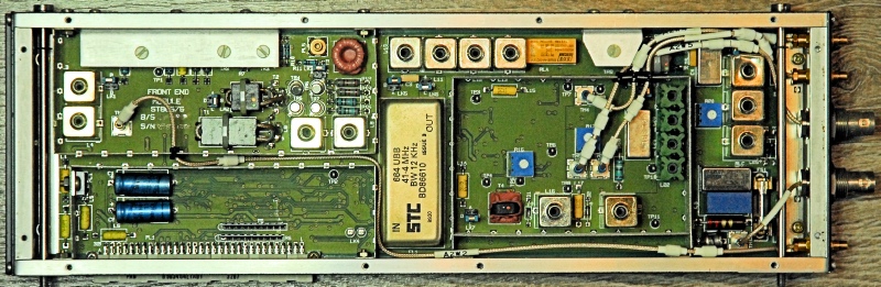
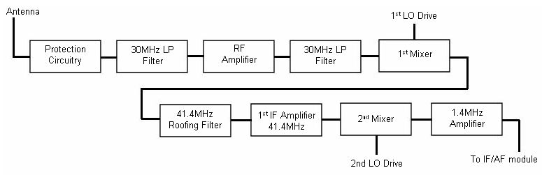
RF Front End
The RA3701 combines into one single module what was spread over three boards in the RA1792. Although the 1st and 2nd mixer circuits are essentially the same, the input protection has been greatly improved and the RF amplifier is now a single-transistor Norton Amplifier. The 1st IF remains at 41MHz, hence the 12KHz bandwidth 41.4MHz filter which dominates the board. The 2nd IF output is at 1.4MHz.
The block diagram above is a grossly simplified representation of the RF Front-End Module. Not shown is the extensive BITE (Built-In-Test-Equipment) which constantly monitors the various supplies and signal levels. There is also a built-in noise source which enables the module-gain to be verified as part of a selected BITE test.
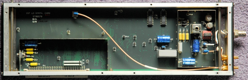
1st LO Synthesiser
At first sight, the 1st LO Synthesiser module can look a little boring. It isn’t until you turn the unit over that you realise the extent of surface-mount technology used in the RA3700 series.
This unit generates the 1st local oscillator signal in the range 41.4MHz to 71.4MHz for injection into the 1st mixer in the Front End Module. The synthesiser is based on a PLL locked to a 20MHz reference produced by the Reference/BFO Module.
Reference/BFO
The Reference/BFO modules looks even less impressive than the 1st LO Synthesiser module. However there’s a lot more going on here than meets the eye.
As it’s name suggests, this module provides a reference signal and the BFO signal, but its a bit more than that. The module can be split into two distinct sections:
a)
i)
ii)
iii)
b)
i)
ii)
iii)
b)
A PLL generating three separate reference signals:
20MHz to the 1st LO Synthesiser Module.
40MHz 2nd LO signal to the Front End Module.
2.5MHz to the BFO section.
A PLL producing a BFO signal that can be tuned over the range 1.4MHz +/- 9.99KHz in 10Hz steps. This signal is passed to the IF/AF module.
20MHz to the 1st LO Synthesiser Module.
40MHz 2nd LO signal to the Front End Module.
2.5MHz to the BFO section.
A PLL producing a BFO signal that can be tuned over the range 1.4MHz +/- 9.99KHz in 10Hz steps. This signal is passed to the IF/AF module.
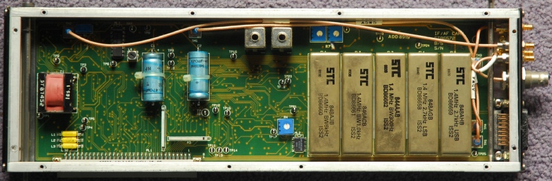
IF/AF Module
The IF/AF Module contains the 2nd IF (1.4MHz) amplifier, IF filters, AGC circuitry and demodulators. The subsequent baseband signal (audio) is then passed to the audio amplifier on the Front Panel PCB. An auxiliary ‘raw’ 1.4MHz output is provided at the rear BNC connector.
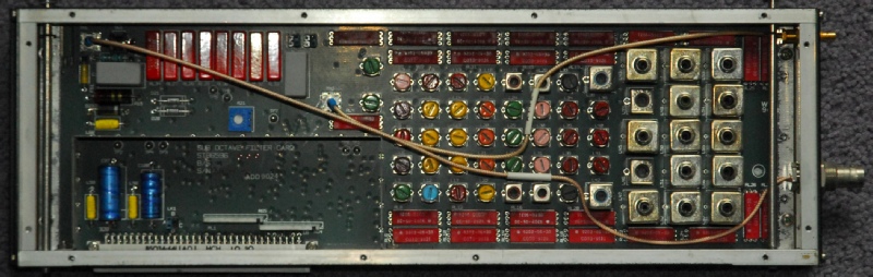
There are numerous Filters sets available. The one pictured is option LA which consists of separate USB and LSB filters with 2.7KHz bandwidth and three symmetrical filters with bandwidths of 300Hz, 1KHz and 6KHz.
There are numerous Filters sets available. The one pictured is option LA which consists of separate USB and LSB filters with 2.7KHz bandwidth and three symmetrical filters with bandwidths of 300Hz, 1KHz and 6KHz.
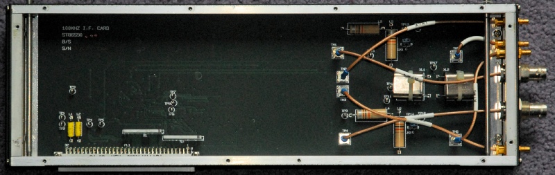
100KHz IF Module
As its name suggests, this module provides an additional IF output at 100KHz for connection to legacy hardware such as the DK-43 Bar-Graph display used by GCHQ.
Sub-Octave Filter Module
This optional module had me scratching my head for some time. Essentially it consists of a 0.6MHz low-pass filter, a 0.6MHz - 1.2MHz band-pass filter and ten Sub-Octave filters between 1.2MHz and 40MHz. These are automatically selected depending on what frequency the receiver is tuned to. This module is thus connected ‘in front’ of the Front-End module to greatly reduce second-order inter-modulation products.
The problem was that in all three 3701s in my possession (at the time), enabling of the Sub Octave Filter (SoF) Module incurred 50dB of attenuation at 1.5MHz. Also, deselecting the Pre-Amp (in the RF Front End) incurred 50dB of attenuation even with the attenuator set to 0dB. This was verified on my Vector Network Analyser, which revealed that the attenuation was 50dB at 1MHz, decreasing to around 30dB at 30MHz.
Such is the rareness of the SoF module, various enquiries regarding this issue drew a blank. However, extensive investigation revealed exactly what was happening. Like the Front End Module, the SoF also has a built-in noise source. When the SoF was activated from the front panel, a genuine Mute line within the module was asserted and the input to the attenuator section was disconnected from the antenna and connected to the noise source, though the noise source itself was not activated. The question was, since firmware in the processor correctly identified the module by way of it’s built-in identifier, why did it fail to work? Further investigation showed that it was in fact the receiver’s continuous BITE software that was the culprit. All the modules ‘sit’ on an 8-bit module-data-bus, and whilst the receiver is running, all 8 bits are active and it was one of these bits that was being ‘latched through’ and muting the SoF.
It was by accident that I eventually identified the problem as ‘firmware-specific’. Whilst investigating a processor module running P87915/14 which ‘crashed’ after a few minutes I hit on the idea of installing an SoF and discovered that particular firmware version did NOT cripple the SoF. As a bonus, I also identified the fault on the Processor module as a failing EPROM. However, I only had one set of P87915/14 and one of the chips was faulty. Fortunately, I was able to copy the contents of the chip in question and then ‘blow’ them onto a new one.
Conclusion:
Although Racal’s brochure states that the RA3700 series supports various optional modules, allowing the user to customise the receiver to their requirements, it does not however state that there are some configurations which are firmware-specific.
Other Optional Modules
These include the following …
IF Filter Module providing up to seven additional filter settings … Also compatible with dual receivers like the 3702 and 3712
FSK Module for FSK reception.
SB Module for ISB reception … also compatible with the IF Filter module.
Audio Module fitted in MA3700 controllers.
10KHz/Signal Detector Module provides an alternative to the detector in the IF/AF module … for COR/SQUELCH operation.
Pan Front End Module for driving an appropriate Panadaptor Display.
Next post in the series: The RA3712 Dual HF Receiver