ISB Adapter type RA218
8 minute read
This post is part of the series 'Sideband Adapters':
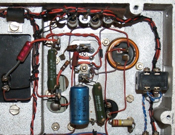
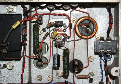
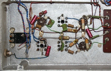
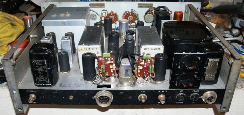
This next area is in fact four different circuits: The 118KHz oscillator, the Mixer, 18KHz Band-Pass Filter and the Sideband Amplifier.
The three elliptical things are the beehive-trimmers for X1 (119.5KHz), X2 (118KHz) and X3 (116.5KHz).
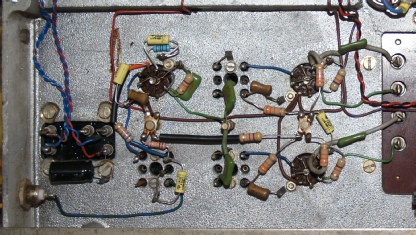
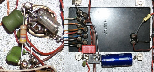
This area encompasses the 18KHz oscillator and the product detectors. Note the valve base in the centre where the components have not been replaced. This is the original 18KHz oscillator which has now been bypassed.
 My thanks to Alan, GM0USI for the photograph below … taken at a distance of only 96cm!
Next post in the series: Racal Sideband Adapters
- ISB Adapter type RA218
- Racal Sideband Adapters
- The Racal RA98
- The Racal RA63
- The Racal RA121
October 2012
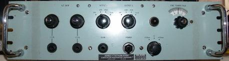
Much can be found on the Internet relating to the RA17’s (or RA117’s) inability to resolve SSB. I think this is actually an unfair criticism since, as I have previously said, the type is more than capable of producing comfortable resolved SSB provided care is taken NOT to overload the detector. This will undoubtedly require judicious use of the input attenuator and IF gain control. Also, bear in mind that a 50 year old receiver with deteriorating resistors and capacitors is NOT going work as well as when it left the factory. Racal made several Sideband adapters. This is the RA218 Independent Sideband Adapter and Fine Tune Unit which was specifically intended for use with the RA117 and was primarily intended for resolving RTTY (or RATT) as part of a system with the designation CJK. The RA218 can also be used with the RA17 or RA17L, however in that circumstance the Fine Tune facility is not used for reasons which will become clear later. This RA218 came to me in a very sad state. I had been warned that it was not complete but that it probably only needed a few valves. True, there were several valves missing; a couple of EK90s and a couple of 12AT7s. Also missing were the two oil-filled 600 ohm output transformers which had been replaced with small output transformers for driving loudspeakers. However the most crucial part that was missing was the 18KHz crystal.
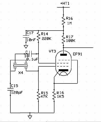
As can be seen from the schematic on the right, the 18KHz crystal, X4 is by no means conventional. For a start 18KHz is literally audio frequency, and anyone who knows anything about quartz crystals will know that a crystal cut to resonate at ten times that frequency will be large. In the RA218, crystals X1, X2 and X3 are all in the region of 118KHz and are all about 50mm high. So to cut one for 18KHz would just be impractical. In fact I even doubt if it would be possible. However, the schematic on the right implies that X4 is NOT actually a single element, but a dual quartz element, cut in such a way that the two resonant frequencies are actually separated by 18KHz ... a very cunning solution indeed.
Obtaining the missing 600 ohm transformers was relatively simple since they are identical to the smaller of the two fitted in the RA17 series. But, it goes without saying that obtaining a genuine 18KHz crystal was going to be a ‘non-starter’. Deciding that I was not going to be beaten, I set about looking for a simple low-cost solution to the problem.
What I came up with is both simple … and appropriately cunning too …
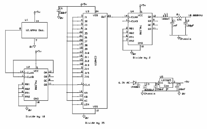
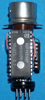
Right from the start I had the idea that I could build something that would actually plug into the B7G socket that the 18KHz crystal had vacated. To facilitate this I would use an off-the-shelf valve extension plug/socket adapter. But first of all, where would the 18KHz come from? What would it be derived from? Rummaging through my box of crystals I came across a couple of 12.6MHz DIP oscillators. A quick calculation confirmed that I was onto something since 12.6 million divided by 18000 is 700 … a nice round figure. The next task was to identify a suitable divide-by-n device … and the CD4059 (or HEF4059BP) looked the part. However the 4059 is limited by the fact that it is not able to handle an input of 12.6MHz. Hence the use of the ubiquitous 74LS90 in divide-by-10 mode. Initially I set the 4059 to divide by 70 but the output, albeit at 18KHz was only a train of very short pulses. Feeding such a train into a second 74LS90 in divide-by-2 form produced a very nice square-wave. Hence, I reset the 4059 to divide by 35. The end result is a very respectable 18.0000KHz square-wave. L1 (100mH) and C1 (1nf) form a low-pas filter whilst R1 (47K) and C2 (120pF) match the resulting sine-wave into the Cathode-Follower (VT5, 12AT7).
The 5V supply is simply derived by half-wave rectifying the heater supply and feeding a 5V regulator. I had to go for a single diode because one side of the heater circuit is connected to the chassis. This makes it impossible to use a bridge rectifier. The entire oscillator/divider circuit only draws 40mA so I was able to get away with a half-wave rectifier and a relatively large reservoir capacitor of 6800uF.
The 5V supply is simply derived by half-wave rectifying the heater supply and feeding a 5V regulator. I had to go for a single diode because one side of the heater circuit is connected to the chassis. This makes it impossible to use a bridge rectifier. The entire oscillator/divider circuit only draws 40mA so I was able to get away with a half-wave rectifier and a relatively large reservoir capacitor of 6800uF.
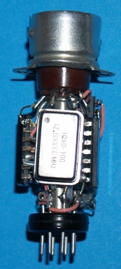
And here it is … the finished solid-state 18KHz generator … probably more accurate than the original since the fundamental is stated (on the can) as 12.600000MHz … and that (and any error) is subsequently divided by 700.
I was able to screw an insulated terminal onto one of the screws securing the valve socket to the chassis, making a nice jumping off point for the matching network. The 120pF capacitor is the original salvaged C15. The original EF91 is still in place but by-passed.
Although I could have used a 78L05, I recycled an old 7805 from the junk-box. Using a larger regulator also makes for more mechanical rigidity/strength.
So now on with the rest of the refurbishment …
I already knew that all the other oscillators functioned, which was a great relief since it would have been very expensive to have any of the big 118KHz crystals manufactured. With the 18KHz generator running nicely, it was gratifying to hear LSB and USB from each of the front panel monitor jacks. The RA218 was doing just what it was designed to do. Its good to have something that works when doing a refurbishment. As with my RA17 series refurbs, I commenced battle with the PSU. I was happy with the main smoothing capacitor, having previously slowly run everything up via a variac. There are no signs that it is leaking DC.
I already knew that all the other oscillators functioned, which was a great relief since it would have been very expensive to have any of the big 118KHz crystals manufactured. With the 18KHz generator running nicely, it was gratifying to hear LSB and USB from each of the front panel monitor jacks. The RA218 was doing just what it was designed to do. Its good to have something that works when doing a refurbishment. As with my RA17 series refurbs, I commenced battle with the PSU. I was happy with the main smoothing capacitor, having previously slowly run everything up via a variac. There are no signs that it is leaking DC.
Before
After
As can be seen, the PSU in the RA218 is of a minimalist nature … in fact about 40% of the components in the photograph relate to the crystal oven relay!
Before
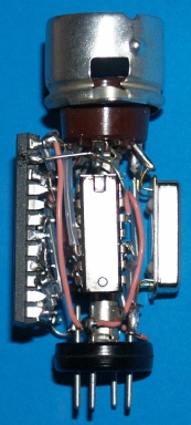
This next area is in fact four different circuits: The 118KHz oscillator, the Mixer, 18KHz Band-Pass Filter and the Sideband Amplifier.
The three elliptical things are the beehive-trimmers for X1 (119.5KHz), X2 (118KHz) and X3 (116.5KHz).
After
Although it can be used in conjunction with the RA17 or RA17L, the RA218 was primarily designed to augment the RA117 by providing a 1.7MHz VFO output to replace the 1.7MHz crystal in the RA117. This allows for a very fine (1KHz) adjustment of the third IF. Curiously this is only +1KHz from the 'Cal' position. I’m not sure why there is no calibrated -ve shift. The design of the 1.7MHz VFO is rather clever in that it involves two crystal oscillators, one of which is a VXO. The crystals are 4.25MHz and 5.1MHz respectively. Both are operated at their second harmonic giving 8.5MHz and 10.2MHz, with the latter being the VXO. Obviously, the difference between the two is 1.7MHz.
Before
After
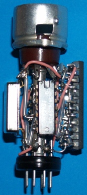
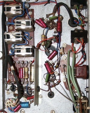
Before
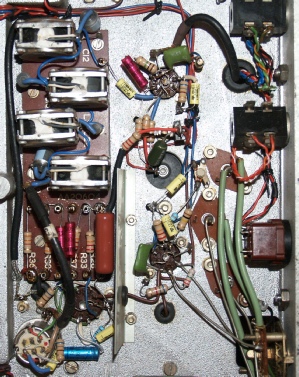
This area encompasses the 18KHz oscillator and the product detectors. Note the valve base in the centre where the components have not been replaced. This is the original 18KHz oscillator which has now been bypassed.
After
So that’s the RA218 finished and fully functional … I’ve even got the mating half of the large multi-way connector (SKT3). This is identical to the one on the rear of the RA1217. Sadly I don’t know the actual serial number since the plate is missing from the rear of the chassis. My next project is to make an interface which will allow the RA218 to take the 100KHz signal from either the RA17, the RA17L, as well as the RA117 and then deliver the SSB to a loudspeaker via a suitable valve amplifier. I could use a solid-state audio PA but somehow the idea just doesn’t sound right!
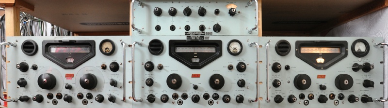
My thanks to Alan, GM0USI for the photograph below … taken at a distance of only 96cm!
RA17 Ser. N664
Note the reflection of my sweatshirt
which was hanging over a chair
off to the left.
Note the reflection of my sweatshirt
which was hanging over a chair
off to the left.
RA17L Ser. N8854
RA117 Ser. N0489
Next post in the series: Racal Sideband Adapters