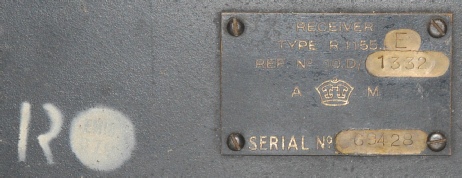
R.1155E Ser. 69428
7 minute read
April 2014
This is the first of two R1155s that I was contracted to refurbish. Actually, I was handed five 1155s and asked to produce two fully working examples. After examining all five, I decided on the ‘E’ and an ‘L’. More on the latter later.
The R1155E is an all-steel version of the R1155A. Aluminium was required for aircraft manufacture and from time to time would be in short supply. Thus, the R1155E was born. Steel 1155s were 6lb heavier than the aluminium version at 32lb, but were still used in airborne applications.
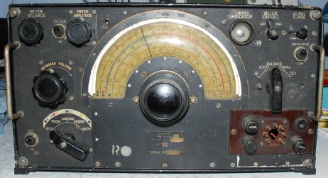
R1155s were produced in huge numbers from early 1940 until 1945. Later models are conspicuous by the fact that most of the front panel decals are painted (silk-screened) on as opposed to screwed on. The exceptions being the range switch decal (because the ‘L’ covered a different range) and the volume and Meter Balance controls which are mounted from the front. This particular R1155E (I have seen a photograph of an ‘E’ with a screw-on range decal) goes one step further by sporting a silk-screened range decal. Look closer any R1155E and you notice that there are no solder tags on the screws securing the valve holders. Instead these have been spot-welded to the steel chassis near-by. This and the total lack of screw-on decals might be perceived as a weight-saving feature but I doubt it. It is more likely that speed of manufacture was the issue.
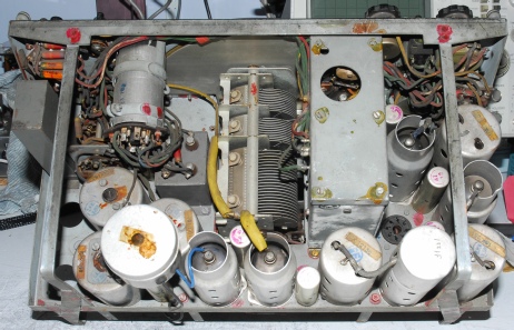
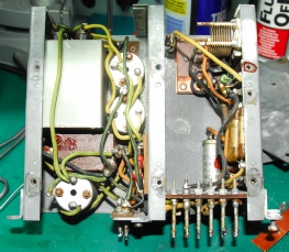
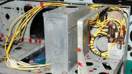
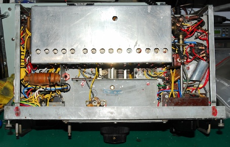
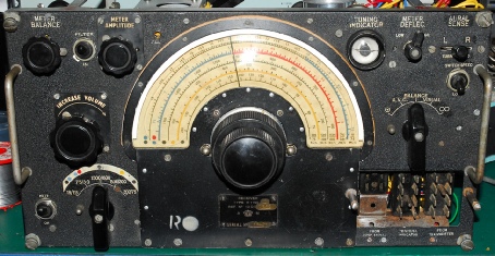
The front panel of this R1155E is in good condition. Only the Het. decal is faded. The Jones Panel had been removed and covered over with a thick sheet of Paxolin. A small aluminium sheet had been screwed over the Jones Panel decals. As can be seen from the bottom photograph, most of the accessible DF circuitry had been removed … i.e. V1, V2 (including bases) and V9, L23, L24, the DF tag-board on the end of the coil-box and three of the iconic tall tubular capacitors. Fortunately none of the switches or potentiometers had been removed. Those DF-associated components in the rear of the BFO compartment were also still present. The Coil-Box lid was however absent. I have reason to believe that the white ‘R’ and disk indicate that this receiver was partially refurbished at a later date … possibly by EMI?
The R1155E is an all-steel version of the R1155A. Aluminium was required for aircraft manufacture and from time to time would be in short supply. Thus, the R1155E was born. Steel 1155s were 6lb heavier than the aluminium version at 32lb, but were still used in airborne applications.
R1155s were produced in huge numbers from early 1940 until 1945. Later models are conspicuous by the fact that most of the front panel decals are painted (silk-screened) on as opposed to screwed on. The exceptions being the range switch decal (because the ‘L’ covered a different range) and the volume and Meter Balance controls which are mounted from the front. This particular R1155E (I have seen a photograph of an ‘E’ with a screw-on range decal) goes one step further by sporting a silk-screened range decal. Look closer any R1155E and you notice that there are no solder tags on the screws securing the valve holders. Instead these have been spot-welded to the steel chassis near-by. This and the total lack of screw-on decals might be perceived as a weight-saving feature but I doubt it. It is more likely that speed of manufacture was the issue.
The front panel of this R1155E is in good condition. Only the Het. decal is faded. The Jones Panel had been removed and covered over with a thick sheet of Paxolin. A small aluminium sheet had been screwed over the Jones Panel decals. As can be seen from the bottom photograph, most of the accessible DF circuitry had been removed … i.e. V1, V2 (including bases) and V9, L23, L24, the DF tag-board on the end of the coil-box and three of the iconic tall tubular capacitors. Fortunately none of the switches or potentiometers had been removed. Those DF-associated components in the rear of the BFO compartment were also still present. The Coil-Box lid was however absent. I have reason to believe that the white ‘R’ and disk indicate that this receiver was partially refurbished at a later date … possibly by EMI?
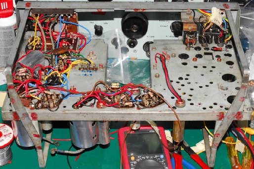
Despite its steel construction, the chassis showed little signs of corrosion. The wiring was also in good condition due to the lack of the dreaded rubber insulated stuff. It is always a bit disconcerting stripping down an R1155, but all of it must come out, if not just to gain access to hidden resistors etc.
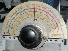
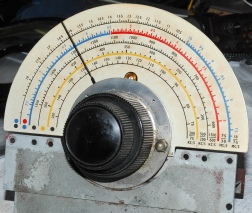
As can be seen, the R1155E doesn’t sport a vernier-type scale around the early Type-13 tuning mechanism. The scale was filthy and showing signs of discolouration. Normally I would remove the scale for cleaning or replacement but the screw securing the course knob was seized solid. I opted not to force it since the mechanism was working perfectly. Better not to disturb it, I concluded. As will be seen in a later photograph, seen through the crescent blister, the scale looks just fine.
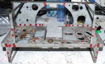
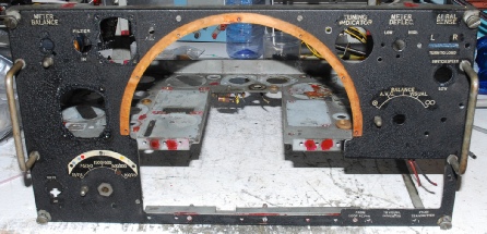
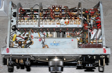
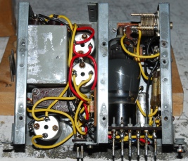
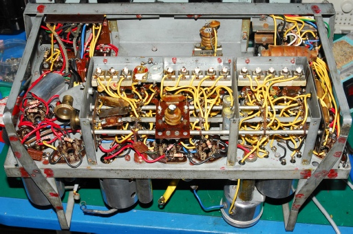
Two photographs of the chassis completely stripped down. I left the cardboard ‘gasket’ in place so as not to damage it. The red ink denotes a ‘spot weld’. At this point in the process, the chassis has yet to be cleaned. There was some corrosion present under the three large RF inductors, L4, L5 and L6. All the rubber grommets will be replaced and any anti-shake shellac will be removed.
Before and after photographs of the BFO/DF compartment. Here I finally encountered the dreaded rubber insulated wire … if it doesn’t crumble to dust on contact, it melts into a horrible stinking goo as soon as the wire heats up. This sub-assembly did exhibit some signs of corrosion but nothing serious. This was cleaned using WD40 and fine abrasive paper. The valve, an original VR101 or MHLD6 was tested on my AVO Valve Tester and found to be good. This self contained assembly can be tested and set aside to be re-fitted later.
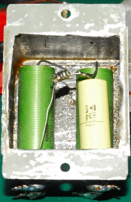
Left … This is the ‘re-stuffed’ inside of the block capacitor (2uF + 2uF + 1uF) in the DF compartment (above).
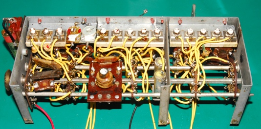
Below … The single-most daunting part of the R1155; the Coil-Box. There are four chassis-mounted 100nF capacitors that need re-stuffing here. I’m sure I would have noticed it before, this being the fourth 1155 that I have tackled, but I suspect the switch mechanism in this unit to be different from others. There is no end-stop! Good job I had five other 1155s to compare it with! That includes my AD8882B.
Left … The BFO/DF compartment refitted along with the ‘Hum Filter’, Volume Control, Meter Balance and Meter Amplitude controls. Note that I have already laced up the wire loom since access will soon become impossible.
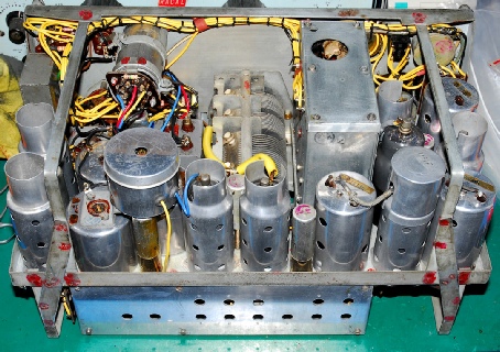
Partially re-built … essentially from the Mixer-Oscillator right up to the audio output.
Not fitted or wired … The Coil-Box, Tuning capacitors (C82, C83 and C84) … L4, L5 and L6, V1 and V2, L23 and L24 and the hideously awkward Master Switch … hence the empty grommets.
This is the fully re-built/re-wired R1155E. At this point … prior to re-fitting the valves which have all been tested it is prudent to make various resistance/continuity checks before applying the 220V.
Finished! Visible in this photograph and salvaged from other R1155s … V1, V2 and associated bases and screening cans … V9 (the extremely rare VR102) … L23, which is actually a transformer … and not forgetting three tall tubular capacitors.
Visible in this photograph and salvaged from other R1155s … L24, which is actually two wave wound inductors in series … the entire Jones Panel assembly and the aluminium Coil-Box lid (because I didn’t have a steel one available). The Jones Panel pillars were obtained via Ebay.
The completed R1155E Ser. 69428.
What’s next? … R1155L Ser. 0138.
Since the ‘L’ was designed for use by aircraft of Coastal Command, it covers a different frequency range. This receiver will take longer to strip down because I will have to write out a new wiring schedule for the coil-box.