Transmitter Type T.1154M Ser. 86102
10 minute read
November 2011
T1154M Ser. 86102
This is the second of two ‘sad’ T1154Ms that I was presented with back in early 2010.
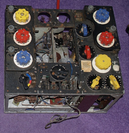
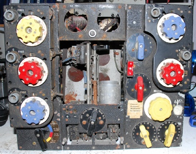
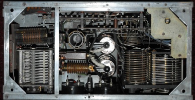
Although it may not appear so, this one was the better of the two, externally. Although not shown in the photograph, both meters, complete with Perspex covers were present, as were the 4 valves. However the ‘Front Door’ was missing and it had been modified ... Note the blue wire dangling out of the PA compartment and the screened wire hanging loose underneath!
The fuse holder was damaged and there was a curious pull-switch retrofitted onto the front panel in the PA compartment, to the left of the ‘Filament Resistance Mod’ label.
Apparently the previous owner, now a ‘Silent Key’ was known to have tinkered with the set and it seemed likely that he had ‘modded’ it in line with one of many ‘improvements’ that were published in the 1950s.
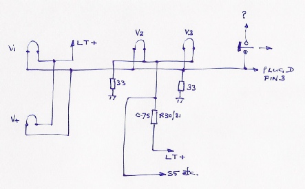
curious heater wiring
Although based on the AD67 and AD77 transmitters (Marconi’s designation for the T1154 was AD87D), and thus a genuine VFO-Controlled transmitter. The T1154 was actually intended to transmit on pre-selected ‘spot’ frequencies which were set prior to a mission, using the Uni-click or less common Multi-click selectors. These were then presumably written in chinagraph on the table on the ‘Front Door’ for quick reference by the W/O (Wireless Operator). With the exception of the MF (Yellow) range, crude fine tuning adjustment was also provided per band by way of a metal lever to the right of the respective VFO control. This was rendered inoperative when ‘FREE’ was selected; in which case the operator could select whatever frequency suited him.
The T1154 is renowned for drifting, and this is perhaps the reason for the curious heater wiring with the additional pull-switch, as in the drawing above. The T1154 did have a means of restricting PA heater current when in Standby (STBI) mode. This is R30/31. It has been suggested to me that this odd heater arrangement was conceived as a way of further controlling the heater current in the VFO (V1, ML6, VT105). Exactly how all this was supposed to work, I have no idea! ... So I set about rewiring the heaters as per the official diagram.
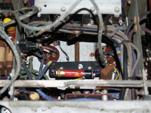
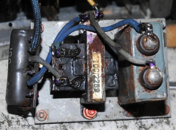
The photograph on the left shows that there were actually two additional screened wires and an additional silvered mica capacitor dangling out of the underside of the transmitter. Apart from that, everything appeared to be present.
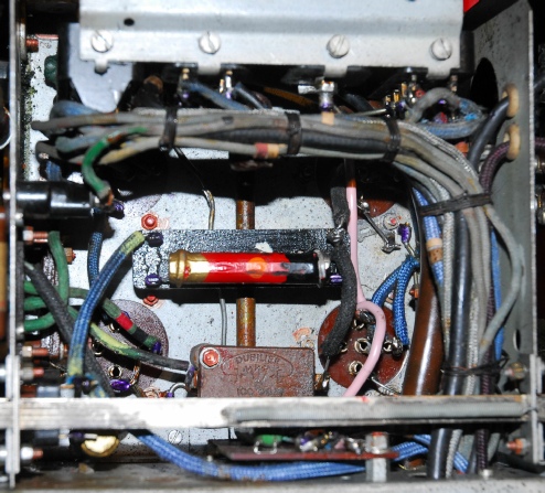
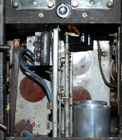
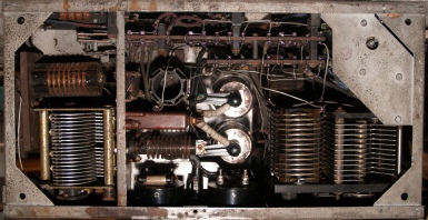
In this photograph the extraneous wiring, capacitor and wiring have been removed, including the two small yellow wires seen in the upper photograph. The heavy pink wire is part of the replacement heater wiring.
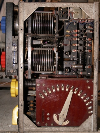
Before and after shots of the inside of the valve compartment
This proved to be rather interesting ...
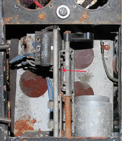
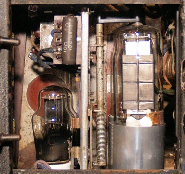
See the photograph on the right. These components are associated with the modulator. As part of the restoration, the block capacitor needs to be ‘re-stuffed’ . It also needs to have the rust removed from its case. In order to do all this, it is first necessary to remove it from within the valve compartment, which is not an easy task! With the T1154, it was a case of ‘once built, never dismantled’. Thus getting access to the various screws securing this little sub-assembly in place actually requires the removal of the two PA-valve top-cap assemblies, particularly the one nearest the rear of the compartment since its bracket completely covers one of the screws. However, see the red arrow in the left photograph and notice that there is a gap between the bracket and the dividing wall in the compartment. This is a manufacturing error. There are two distinct top-cap assemblies with different stores numbers. The top-caps themselves are not identical since the HT-lead exit-holes have to face each other. In the case of the rear assembly there is also a hole in the mounting plate to give access to the head of one of the screws securing the modulator component sub-assembly. In this case, the top-caps had been transposed so that when the top-cap assemblies were fitted into the compartment, and this would be after the modulator components were fitted, the top-cap assemblies were in fact reversed. In this case, the one nearest the front had the extra hole. The rear one didn’t therefore and thus when secured to the dividing wall, the plate buckled as it fouled on the screw head. To rectify this 70-year-old mistake, I carefully dismantled both top-cap-assemblies and reassembled them correctly ... giving them a good wire-brushing at the same time to get rid of the rust.
See the photograph on the right. These components are associated with the modulator. As part of the restoration, the block capacitor needs to be ‘re-stuffed’ . It also needs to have the rust removed from its case. In order to do all this, it is first necessary to remove it from within the valve compartment, which is not an easy task! With the T1154, it was a case of ‘once built, never dismantled’. Thus getting access to the various screws securing this little sub-assembly in place actually requires the removal of the two PA-valve top-cap assemblies, particularly the one nearest the rear of the compartment since its bracket completely covers one of the screws. However, see the red arrow in the left photograph and notice that there is a gap between the bracket and the dividing wall in the compartment. This is a manufacturing error. There are two distinct top-cap assemblies with different stores numbers. The top-caps themselves are not identical since the HT-lead exit-holes have to face each other. In the case of the rear assembly there is also a hole in the mounting plate to give access to the head of one of the screws securing the modulator component sub-assembly. In this case, the top-caps had been transposed so that when the top-cap assemblies were fitted into the compartment, and this would be after the modulator components were fitted, the top-cap assemblies were in fact reversed. In this case, the one nearest the front had the extra hole. The rear one didn’t therefore and thus when secured to the dividing wall, the plate buckled as it fouled on the screw head. To rectify this 70-year-old mistake, I carefully dismantled both top-cap-assemblies and reassembled them correctly ... giving them a good wire-brushing at the same time to get rid of the rust.
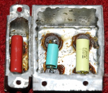
Left ... There are only three capacitors in the T1154 which warrant summary re-stuffing and two of these are contained within the same ‘block’
Below ... Before and after shots of T1154M Ser. 86102
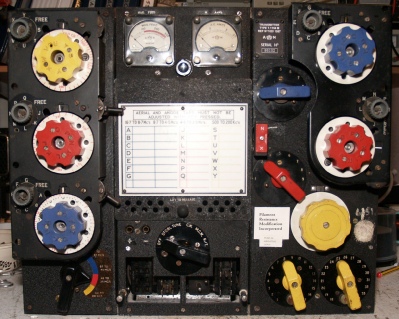
Quite a transformation ... The set cleaned up rather well! Like on my own 1154, the serial number plate is recreated on paper. In this case, the original shellac covering was so badly discoloured and wrinkled that any attempt to clean it would have destroyed it. So I simply reversed the plate and stuck a paper copy on top. Similarly, the ‘Filament mod’ and ‘Fuse mod’ labels to the left of the Yellow Range variometer are modern versions. Unlike my one though, there has been no requirement to re-spray anything; instead, in most areas, a damp cloth was all that was required and wherever there was any paint that had actually flaked off, I found that black acrylic paint when applied with a stiff bristled brush, did the business. The front door is actually the original from my own T1154. I only realised this when cleaning this one up. I found that the serial number 85660 is painted on the inside surface of the door! Since my own transmitter had to have its front more or less fully re-sprayed, I felt that it would actually look odd with a rough textured front door, so I have opted to keep with the home made door on mine and transfer the original to this one ... as in the photograph.
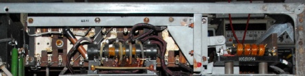
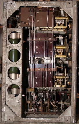
Above, inside rear of Ser. 86102 ... Below, note extra metalwork in Ser. 85660
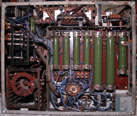
It could be said that the photograph on the left might be described as iconic. The reason being, that the seven large vitreous enamelled high power resistors are what most people associate with the T1154 (ignoring the brightly coloured knobs!). If you do the maths, there isn’t really a lot of dissipation going on either. Some of them are only dissipating about 3W, while some are as high as 25W. The reason why they are there is because the design of the transmitter is so simple. Or rather, the PSU powering it is so simple ... 1200V and 6V. Thus, the resistors serve as voltage divider networks to provide the lower voltages for the Master Oscillator and Modulator/Side-Tone Oscillator and biasing for the PA valves. In this case, when carrying out the resistance checks as per A.P.2548A, I found that two of these big resistors (the one on the left and the one on the right) were open-circuit. I am indebted to Michael Milne for his generosity in providing me with replacements. I have to admit to being curious as to how two of these resistors can end up open circuit whilst showing no external signs of stress. I can only surmise that an internal fault occurred. The wire from the end-connection to the resistance wire itself is NOT part of the ‘resistance element’. I also noticed that there is a slight mechanical difference between the two T1154Ms. See the photographs left and below.
T1154M Ser. 85660
T1154M Ser. 86102
I know that at the peak of Bomber Command’s campaign, (November 1943 until early 1945), fuel was often sacrificed in favour of bomb load. However the differences between the two transmitters above are so insignificant, it is more likely that speed of manufacture was more likely to be the reason for the removal of the bracket on the band-change switch and the change of shape for the relay mounting plate. Although not in the photograph, Ser. 85660 does have a capacitor across the Mag Feed meter.
Three more photographs of Ser. 86102. The transmitter worked perfectly first time, I am happy to say.
All that needs to be done now is to clean up the cabinet.
The frequency calibration on this one and mine is somewhat dubious, but I plan on looking into resetting the MO dials.
Two Triodes and two paralleled Pentodes
Personal Historical Note ...
Growing up during the heat of the cold war and being of an impressionable age in the mid 1960s, I suppose it was inevitable that I would develop an interest in WW2. My own father was in the ATC as a teenager in Leith when WW2 broke out and therefore was more or less guaranteed to be called up for RAF service. He wore glasses though, so was told he was likely to be trained as a flight engineer if selected for aircrew. However, he was too young for call-up at the start of the war and by 1944 when he finally received his ‘papers’, Bomber Command actually had an excess of aircrew, so he was drafted into the army instead and served in the Royal Scots. Six weeks before VE day, he landed in India where he served out his time in the services behind a desk, attaining the rank of sergeant.
Between 1939 and 1945, more than fifty-five thousand Bomber Command aircrew were killed in action ... NOT including those wounded (some severely) or captured. How different things might have turned out had my father been born a year or two earlier.