R.1155L Ser. 0138
9 minute read
October 2014
This is the second of two 1155s that I was ‘contracted’ to restore for a friend. Since I had previously restored an R1155E with the Type 13 tuning drive, I figured that the second one should feature the later Type 35 drive. Despite sporting a couple of obvious modifications, this R1155L was an obvious choice; for two reasons. The first being that since the ‘L’ was intended for Maritime use by Coastal Command, it covered a different set of frequencies. Gone is 75KHz to 200KHz while 1.5MHz to 3MHz is added. The second reason for choosing this one was the super-smooth and light tuning action. It is actually possible to spin the fine-tune part of the knob and watch as the pointer continues to traverse the scale.
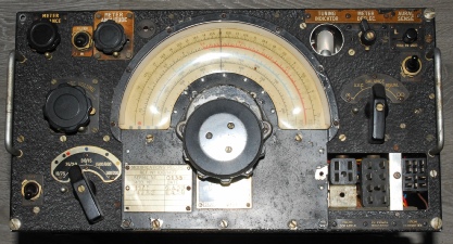
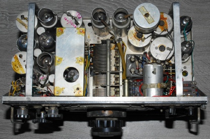
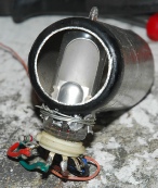
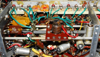
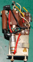
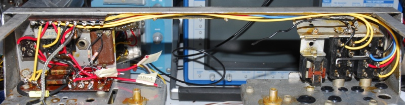
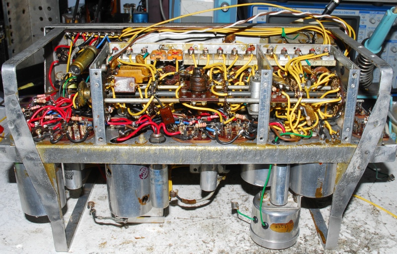
The photographs on the right shows the condition in which it was received. Note that it came with a full compliment of valves. As well as the odd modification to the ‘Tuning Eye’, one of the two 8-way Jones connectors had been replaced with a different type. The screening cap for the 1st IF valve was missing, but apart from that, the critical components were present. These being the two wave-wound inductors comprising L24 and the transformer that is curiously identified as L23.
Also, the two triple capacitors in the DF circuit had been replaced with six discrete capacitors and the tall 4uF block capacitor had been replaced with a more modern 16uF type. The side plate for the BFO/DF compartment was missing as was the block capacitor in the DF section. There was also an additional capacitor in the BFO section. However, because of its different frequency coverage, this was not going to be a straight-forward restoration. I would have to pay close attention to the wiring in the coil-box and make appropriate notes prior to re-building the set with the help of Peter Holtham’s excellent book on the subject. The plan was also to feed back to Peter for future updates.
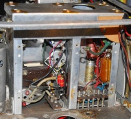
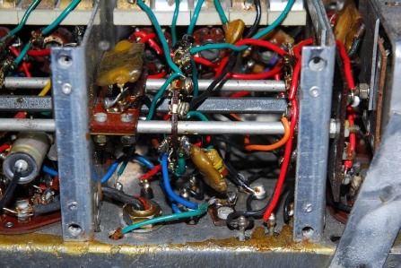
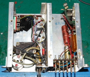
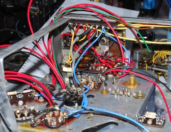
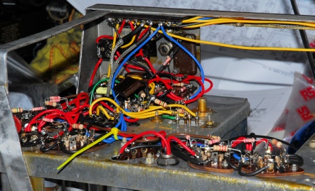
The difference between the R1155L (and N) and other models is thankfully limited to the Coil-Box. L6, L11 and L18 are replaced with L40, L41 and L42. Refer to chapter 35 in A.P.2548A for a detailed description of the changes. A rat’s nest at the best of times, this one was no exception. Judging by the nature of the wiring, I have to conclude that someone had been there before me and replaced the old rubber or cloth covered solid core stuff with brightly coloured PVC-covered multi-strand wire. This may be have been carried out in 1958. There is a service label on the front panel with two entries dated 1958. My task was to carefully dismantle each section in the Coil-Box, keeping careful note of the wiring, whilst comparing it with the circuit diagram and then drawing the wiring routing along the lines of that shown in Peter Holtham’s book.
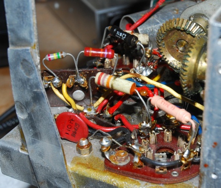
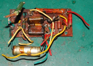
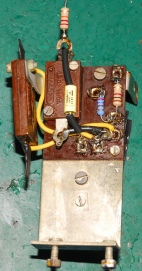
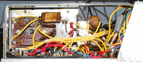
The vitreous enamelled resistor (right) between the 9-way tag board and the bias tag-board was initially thought to be a ‘new’ addition but turned out to be a repair, replacing R3 on the bias board.
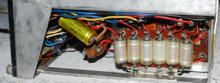
Most of the 1940s vintage resistors had been replaced as the photograph on the left shows … five different styles in the area of the second IF amplifier alone!
Like in the DF circuit, some of the 0.1uF capacitors had been replaced.
Once the radio is stripped down to a bare chassis and all the bits and pieces are carefully bagged and labelled, the restoration process can begin. The following images show just a few of the sub-assemblies, before and after re-work.
Left: Bias Tag-Board before
Right: Bias Tag-Board after
Left: Bias Tag-Board before
Right: Bias Tag-Board after
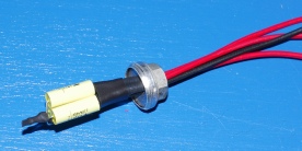
An example of a re-stuffed triple capacitor
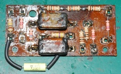
This is the Audio Filter, sometimes referred to as the hum-filter.
Left: before
Right: after
As mentioned earlier, the BFO/DF compartment had been worked on somewhat. During re-work I found that one of the stacked capacitors at the bottom of the DF sub-compartment was short-circuit. Also, most of the tags on the BFO board itself were broken. I managed to salvage a replacement board, a 5nF capacitor and a block capacitor from a couple of scrap units.
The first assemblies to be re-fitted and wired up are the 9-way tag-board and the Jones Panel, followed by the Bias tag-board, the audio output transformer, the Het On switch, C103, R9 and R68.
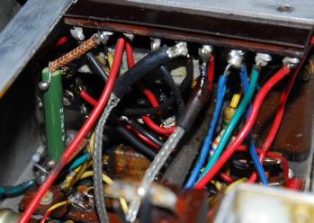
The BFO/DF module can then be re-fitted along with the valve sockets and tall tubular capacitors in the IF/AF section … followed by the heater (LT+) wiring, in blue. The photograph above right shows the chassis wiring complete from the RF amplifier up to the audio stage.
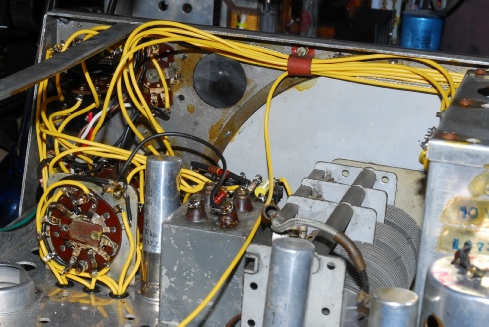
The wiring around the Master Switch can be very daunting … perhaps more so than the Coil-Box. Whereas the coil-box can be re-wired off the main chassis, the Master Switch must be wired more or less ‘in situ’. At this point L23, C56, the chassis mounted block capacitor and the remaining front-panel switches are fitted and wired up.
The coil-box which was re-wired earlier can now be fitted. However, Inductors L4, L5 and L40 first need to be screwed to the chassis. An obvious question at this point is ‘with the coil-box in place, how does one actually solder the necessary wires in place?’ I find that with the rear of the coil box propped up by about 15mm, it isn’t too difficult to get the soldering iron into the space below.
The penultimate area of circuitry to be done is that associated with V1 and v2. This involves threading a bundle of wired up though the largest of the rubber grommets next to the Master Switch. The bulk of these wires go to L23.
Note that I fitted the two static-bleed resistors but left them disconnected from the antenna terminals.
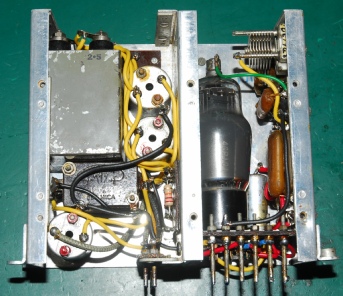
Finally, V10 can be wired up and the wire bundles neatly laced. It is though a good idea to align and test the receiver before applying the lacing cord. The only item missing is the screening cap from the top of the 1st IF valve (bottom right).
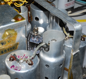
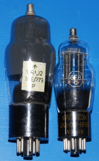
Those with sharp eyes will also have spotted that V9 is not a VR102 (BL63). Several years ago I spent some time looking for a suitable alternative for the nearly impossible to find VR102 and I came across the 6F8G which is pin-for-pin identical. Specification-wise, being designed as an audio amplifier it does differ from the VR102, which I believe was not. However, in the R1155, the double triode is simply used to drive the twin movements in the Visual Indicator. The diminutive 6F8G performs this simple task with ease whilst drawing about half the heater current of the VR102. Be aware that 6F8Gs are, like many WW2-era valves, loved by audiophiles. So although easy to find, they do sometimes cost up to £25 each … but still a lot less than VR102s go for!
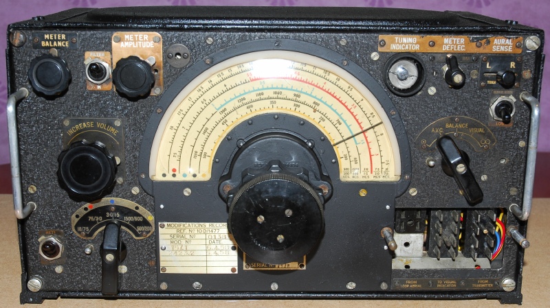
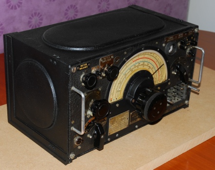
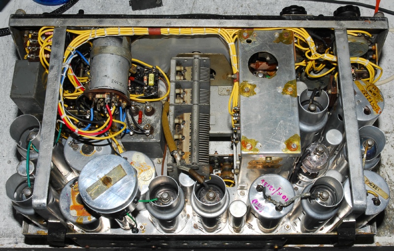
A couple of photographs of the finished receiver. I think it looks quite good with the textured paint on the case. Overall sensitivity is very good indeed with the NDB at Prestwick on 355KHz being picked up at a distance of 80Km! Curiously, when using the RF gain option (omni) the useable audio appears to be confined to the last 50% of the control travel. The AGC voltage swing is as per document A.P.2548A so I have to conclude that this anomaly is down to valve characteristics etc. I cannot find anything wrong. Also as per other 1155s, the holes in the coil-box lid are marked for the individual bands (although access for adjustment is recommended via the holes in the front of the box). I recorded the coil-box wiring during the strip-down process checking each position on the switch and detailing which trimmer capacitor and inductor was selected. However the end result does not appear to agree with the numbers adjacent to the holes in the lid. At first sight this might be a bit alarming, indicating a wiring error. But all the bands tuned up. The tuning scale is as accurate as can be expected and as previously said, the sensitivity and audio output is very good.