Repairing a troublesome ProSisTel Rotator
16 minute read
... and how the quality of components matters.
May 2020
Two years ago I invested in a Yaesu G-1000DX rotator to replace a very troublesome ProSisTel PST641 that I had resurrected from a box of bits (literally) back in 2009. The latter had belonged to a friend who rather unfortunately, had suffered more than a couple of mast failures. I can't remember if the PST641 was involved in all the collapses, but it finally broke apart when vandals toppled his mast. Unfortunately there had never been any lateral support and the bottom casting shattered.
Not being one to turn down a challenge, I retrieved the bits, glued the bottom casting back together and fashioned an exoskeleton to wrap around the casting for extra support. The top plate was bent and a friend kindly arranged for this to be corrected. I'm told this involved a lot of heat and a sledge-hammer!
With the PST641 resurrected, it was installed in the cage atop my Tennamast, and there it happily turned far too many antennas for several months. It can get rather windy here during the winter months and the mast is frequently lowered to half-height from time to time. After one paticularly stormy couple of weeks when the mast was down the whole time, I discovered that I no longer had reliable control over the rotator. This was traced to a failure of the feedback potentiomer in the base of the rotator. The underside of the rotator is not weather-proofed and water had been blown in by the strong winds that we get in these parts. I replaced the 'pot' with a new 10K one and all was well ... for a while. Again, I lost control and naturally blamed the feedback potentiometer. However on examination, the pot was intact, although there was quite a bit of evidence of water ingress. I had never been happy with the square connector that ProSisTel fitted to the control cable. I found it very difficult to make weather-proof. So I simply replaced it with connector blocks wrapped in self-amalgamating tape.
The mast was wound back up, and all was well ... for a few days ... when I lost control yet again. Down came the mast ... again. This time the feedback potentiometer really had failed. So it was replaced. This process: Replacing the feedback potentiometer was repeated several times over the next few years. I can't say for sure that it was a pot-failure every time I lost control, but I got to the point where I replaced it as a matter of course.
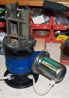
The PST641 after repair in 2009
Actually, the PST641 was in service at the top of my Tennamast for almost ten years between 2009 and 2018, which isn't half bad considering it was a 'bucket-job' when I got it. A few years ago I had to re-make the exoskeleton which had cracked. Then to further strengthen the bottom casting I inserted a cardboard tube around the feedback pot and filled the gap between the tube and the casting with epoxy resin. This worked really well too. However the problem with sporadic loss of control never went away, so in 2018 I decided to pension the ProSisTel off and bought the G-1000DX, in which I have full confidence.
And so, the PST641 and its very nice talking controller have sat in a box under our stairs ever since ... until this week, when I decided to get to the bottom of the 'loss of control' problem. I should say at this point that whenever the issue occurred the symptoms were always the same: Failure to respond to azimuth bearings entered on the keypad and only able to drive the rotator (blind) in one direction from the keypad.
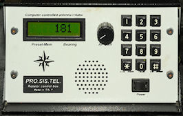
Model 'C' Controller
I didn't get a manual with the rotator, after all, I retrieved it from the bin. I actually have three downloaded manuals though, which may sound a bit excessive. However, ProSisTel don't generally supply circuit diagrams with their hardware and since I was not going to return the item for repair, I had gone searching on the internet for as much information that I could find. The manual for the PST641 covers all the different controllers descriptively, but does not provide circuit diagrams. However another manual that I have does include the schematic for one of the other controllers and from that I was able to figure out how the rotator control PCB worked.
Getting access to the board is far from easy. The controller case is extremely solid but has not been designed with easy access in mind. In order to take the rotator control board out you first need to remove the top and bottom covers. They're easy ... four big self-tapping screws apiece. Then you have to remove one of the side panels. Slighty harder here ... two screws and nuts at the back, two screws tapped into hank-bushes at the bottom and two Allen screws at the front. However one of the latter is tapped into a pillar supporting the processor board, whilst the other has a nut and washer on the inside. Where's the consistency? Having taken all these screws out we now have access to the board ... which is supported on four metal pillars. However, again there is a lack of consistency. Some of the pillars are held onto the chassis by screws and some by nuts.
7805 regulator
At this point I notice that there is a TO-220 regulator screwed to the chassis but wired to the board. Unlike some ProSisTel rotators where the feedback pot is connected across a single 5V source, the model 'C' controller applies +12V to one end of the pot and -12V to the other. This 'split' supply also powers the comparator circuit on the control board. My initial guess was that what I have is a very early incarnation of the model 'C' controller where the additional regulator is an addition to an earlier design. However the additional regulator turns out to be a 7805, so not directly related to the actual rotator.
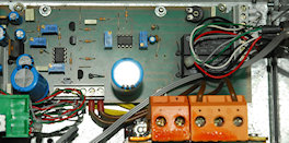
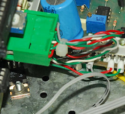
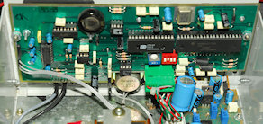
Rotator Control Board
Two further photographs of the inside of the controller. The control board differs slightly from the drawing in the manual.
Processor and display board
So having compared the board to the only schematic that I could find (one relating to a different board altogether), I had a good idea of what did what. The chip on the left and the three horizontally mounted trimmers form the comparator circuit where the upper and lower multi-turn trimmers set the CW and CCW limits of rotator travel. The wiper of the middle potentiometer is connected to an unused terminal on the board. The chip in the centre with the two vertically mounted trimmers is described as a voltage amplifier for intefacing with a computer interface ... although it did not appear to be connected to the 9-Way connector on the rear panel, nor does it appear to have any effect on the operation of the box. The four TO-92 transistors are BC337s and form the relay driving circuits. At this point I got rather confused since to me it appeared that all four BC337s were mounted back-to-front ... until I discovered that I had two different data-sheets each showing a different pin-out. Either one was a misprint or pin-out can vary depending on manufacturer ... hmmm?
The PST641 uses a DC motor and the two relays for delivering the current and reversing it are on the right. The black trimmer resistor above the relays is a repair (see text).
At this point in my investigation, the rotator would only drive in one direction. This was good since I hate intermittent faults. I identified the CW and CCW control lines from the Processor board and disconnected them from the controller. Each of these simply connects to the Emitter of the appropriate BC337. Grounding each one in turn would normally cause the motor to drive in one direction or the other ... but not in this case.
The fault turned out to be a fracture in the PCB track between the Collector of one transistor and the Base of the next. This was easily repaired by scraping off the solder-resist on the track and re-flowing the joint to cover the crack. It was then possible to drive the motor in both directions. I reconnected the processor board to the control board ... but we were still not out of the woods, so to speak.
The last time I had changed the feedback pot I had fitted a 5K one by mistake, so I had ordered a 10K one and duly fitted it. I should add here that I did fit the correct model of Bourns potentiometer. So imagine my frustration when I found that 360 degrees of azimuthal demand resulted in something like 380 degrees of actual travel!
Which brings us to the potentiometer 'repair' mentioned earlier. This 100-ohm pot is supposed to allow the user to apply up to 15 degrees of offset to cater for slight misalignment of antennas on the mast. Curious to see what effect the control actually had, I gave it a tweak. Or rather, attempted to. It was siezed solid. Hence why I replaced it. It did exactly what the manual said it would do, so that didn't resolve the excessive travel ... I didn't expect it to either. Interestingly, I read that later models of the controller don't have this pot.
A search of the internet failed to provide any instances of my problem. However my search did produce various reviews of ProSisTel rotators and descriptions of how they operate. A common theme was that the feedback pot is a 10-turn pot of which only one turn is used. This makes perfect sense and is far simpler and less expensive than other solutions where a network of gears is used to reduce 360 degrees down to 290 or thereabouts. It was becoming clear to me that my brand-new 10-turn 10K pot was either closer to 11-turns or there was an issue with the linearity.
So I removed the 10K pot and refitted the 5K one that I had just removed ... BINGO! 360 degrees of travel, give or take a degree. In actual fact, 5K or 10K, it makes no difference ... and I have read that some third-party suppliers will replace the 10K pot with a 500-ohm pot 'to improve accuracy'. In hind-sight, the most common use of panel-mounted 10-turn potentiometers is simply to provide very precise control ... the number of complete turns is usually of no consequence. I'm certain there are potentiometers out there with exact degrees of travel offering fantastic accuracy at prices to match!
1nF/6KV
Whilst testing the rotator another problem struck. This time the motor stopped and the controller emitted a low hum ... not good. This turned out to be a short-circuit 1nF capacitor across the DC motor. On-load, the voltage across the motor is about 18V and looking at the capacitor that had failed it looked no different to a common 50V 1nF capacitor. I'm only assuming that it was 1nF as I can't read the markings. Given the brutal back-emf than can be present across induction motors, I did feel that a 50V capacitor was a bit underrated ... so I fitted a 6KV rated capacitor ... simply because I had some. There are other capacitors connected to the motor whose function is a mystery to me. As well as the one across the terminals, each terminal is connected to the motor's metal body via a 100nF ceramic capacitor and 10nF (polyester?). If the motor body was actually grounded I could see their function, however there is no earth connection anywhere within the rotator. So if anything, these capacitors only serve to transmit any transient spikes onto the body of the motor and any other metal that it is in good contact with.
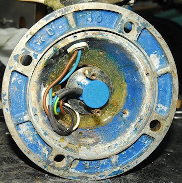
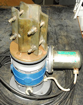
The Feedback Potentiometer
Having cleaned up the rotator, removing all flaky paint and as much aluminium oxide as was possible and then re-painting various parts, I was very happy with the result. In my mind the PST641 was working perfectly. But then another problem struck! I could drive it in either direction using the CW and CCW buttons but entering an actual figure gave eratic results with it frequently stopping prematurely. Putting the controller into 'absolute mode' showed that the voltage on the wiper of the feedback pot was inconsistant. This turned out to be a problem with the feedback potentiometer itself ... no surprises then! The photograph on the left shows the potentiometer in the bottom casting. Note the ring of epoxy filler adding strength to the repaired casting. You can also make out some of the screws from the external exoskeleton. The potentiometer is mounted on a steel disc. Two pillars are then used to attach the assembly to the bottom plate (which has been removed at this point). I was able to resolve the problem by squirting De-Oxit down the shaft of the potentiometer in the hope that it disolved any dirt or corrosion that might be impeding the contact between the wiper and the track.
Although it worked and the rotator is working again, I believe that the mechanical arrangement of the feedback potentiometer is inherently flawed. Firstly, the shaft of the pot needs to be drilled to take a T-bar. The shaft of the pot is then pushed up inside the output shaft of the rotator ... a slot in the output shaft matches the T-bar and thus turns the feedback pot accordingly. However when the potentiometer assembly is screwed onto the bottom plate there is the possibility that the shaft of the potentiometer is actually partially pulled out of the slotted hole in the rotator output shaft.
This is a problem for two reasons. Firstly, the actual position of the T-bar with respect to the end of the shaft is not specified, and should it be fitted half-way between the mounting plate and the end of the shaft, then it might just be possible for the T-bar to not actually fit in the slot should the shaft pull back far enough. Secondly, and this might actually highlight a quality issue with Bourns potentiometers, but I have found that these 10-turn pots are actually prone to 'noise' problems caused by excessive longitudinal shaft movement. This can be minimised by ensuring positive pressure on the shaft. i.e. pushing on the shaft when turning. To ensure minimal longitudinal shaft movement I have made sure that the potentiometer shaft is fully inserted into the output shaft. I then measured the distance between the support pillars and the bottom plate ... typically 1.5mm, and fitted appropriate spacers, thus ensuring that the potentiometer shaft does not move inside the output shaft. So far this solution appears to work.
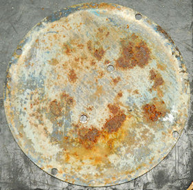
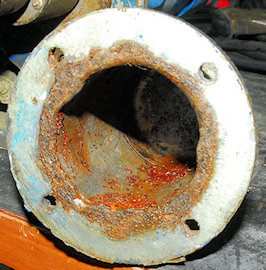
Bottom Plate
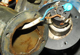
Weather-proofing issues:
The fit of the bottom plate is such that water ingress is an inevitability. It would probably be wise to apply a generous amount of external sealant around the circumference. The motor housing is also prone to water ingress. Note the pools of rust! I have since made a thin rubber gasket for the flange. The issue is not really surprising since the cable-gland is simply screwed into the side of the steel enclosure ... a flat face against a curve ... Never going to be water-tight!
Motor Cover
PST-641 repaired 2020
Final thoughts:
Despite all the problems that I have had with it, I don't dislike the PST-641. It actually has a lot going for it. Mechanically the actual rotator is extremely rugged and strong, especially if afforded suitable lateral support (which this one was originally denied). I cannot speak for current models but given the amount of water ingress I would say that the design does not cope well with wet and windy Northern Latitudes. I also read that some of the current ProSisTel rotators now come with Hall-Effect positional feedback, eliminating the need for a feedback potentiometer. Treat it well and the PST-641 will probably serve you well but it is probably what I would call a 'high maintenance' item. Given that most radio hams love to tinker, that's maybe not a poroblem ... hi! hi!