Restoration of a MKI Racal RA17
27 minute read
The repair and restoration of RA17 N664
January 2009
The Racal RA17 is undoubtedly the product which firmly established Racal as a world leader in its field. Had it not been for Collins’ unwillingness to allow Racal to manufacture their product under licence using non-US sourced parts, the RA17 might never have been designed.
As a former Racal Defence man myself, I felt it appropriate, and indeed a challenge to restore a very sad looking early RA17 (Ser. No. N664). Inspired by Peter Holtham’s detailed account of the complete restoration of an RA117 (here) I decided to perform the same ‘operation' on my RA17. The task was nowhere near as difficult as I had expected. What I found when examining the resistors and capacitors that I replaced only confirmed that this was a worthwhile task. I hope that the following pages inspire others as much as Peter’s inspired me.
As a former Racal Defence man myself, I felt it appropriate, and indeed a challenge to restore a very sad looking early RA17 (Ser. No. N664). Inspired by Peter Holtham’s detailed account of the complete restoration of an RA117 (here) I decided to perform the same ‘operation' on my RA17. The task was nowhere near as difficult as I had expected. What I found when examining the resistors and capacitors that I replaced only confirmed that this was a worthwhile task. I hope that the following pages inspire others as much as Peter’s inspired me.
Initial Fault Survey
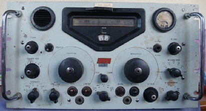
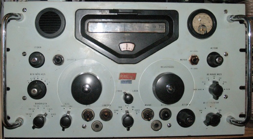
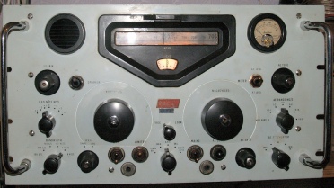
As can be seen from the photograph (right), it was in a very sorry state indeed. Lying for over a year in a damp unoccupied property had probably not done it any favours. The front panel was splattered with some unknown substance. Interestingly though, when I switched it on, it did work, sort of. There was a lot of noise and crackles etc. Sensitivity was low, and the resolved audio was exceedingly distorted. Never having heard an RA17 in operation I had no bench mark to compare it with. However, I had recently read that many fans of the RA17 swear that they can still out-perform many of today’s modern receivers. With this in mind, and with a newly repaired RA1772 in the shack, I decided to put it to the test. But first I was going to have to do some serious work!
Note that the switch knobs in the photograph above are not the more common skirted type. This and the low serial number (N664) lead me to think that this is possibly a MK1. It took me a long time but I eventually stumbled upon Steve’s Boatanchors RA17 page (no longer live), where the first three pictures are of a MK1 RA17 (Ser No. N721) ... Complete with non-skirted knobs. So I reckon mine is definitely a MK1.
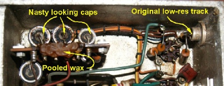
Obviously before embarking on this project I needed to get myself a manual and circuit diagram. The first one that I found was for an RA17L which I downloaded mainly out of curiosity. I eventually located and downloaded an RA17 manual with a very nice circuit diagram which I printed out on eight A4 sheets and carefully taped together. At his point, having cleaned up the front panel and with the lid removed, I switched it on again. Something caught my eye. A wisp of smoke. Not a good sign! I switched it off. Turning it upside down and removing the main bottom panel, it was clear where the smoke was coming from. But not only that, the tag-board in question was bent. Further examination revealed that one of the screws securing the side gusset plate to the chassis was too long and was pushing the board away from the chassis. At some point, the side plate adjacent to the 100KHz module had obviously been removed and when re-fitted, one of the long screws was substituted for one of the shorter ones. This however was not the cause of the smoke. R80 (2K2) in the 100KHz IF strip was completely cooked and was now only measuring 200R. A quick investigation revealed that the resistance to chassis from the ‘cold’ end of R80 was only about 400R. This implied about 200V across R80! 18W dissipated in a half-watt resistor is bad news! The actual cause of this low resistance fault was most unusual. I ‘chased’ it back through the 100KHz and Xtal filers. The input to the latter comes from the 3rd mixer via PL6 on the 2nd VFO module. Disconnecting SK6 from PL6 removed the fault. PL6 is connected to the Anode of V11 via R79 (2K2). However there was a low resistance evident across PL6 which was cleared simply by cleaning the rear of PL6. Inside the 2nd VFO unit there is a small vertically mounted tag board. In this case it was clear that several of the resistors had been severely stressed and showing signs of ‘cooking’. Huge amounts of wax had pooled towards the bottom edge of the board. It is my belief that waxy smoke had contaminated the rear of PL6 and formed a low resistance path to chassis.
Note that the switch knobs in the photograph above are not the more common skirted type. This and the low serial number (N664) lead me to think that this is possibly a MK1. It took me a long time but I eventually stumbled upon Steve’s Boatanchors RA17 page (no longer live), where the first three pictures are of a MK1 RA17 (Ser No. N721) ... Complete with non-skirted knobs. So I reckon mine is definitely a MK1.
Obviously before embarking on this project I needed to get myself a manual and circuit diagram. The first one that I found was for an RA17L which I downloaded mainly out of curiosity. I eventually located and downloaded an RA17 manual with a very nice circuit diagram which I printed out on eight A4 sheets and carefully taped together. At his point, having cleaned up the front panel and with the lid removed, I switched it on again. Something caught my eye. A wisp of smoke. Not a good sign! I switched it off. Turning it upside down and removing the main bottom panel, it was clear where the smoke was coming from. But not only that, the tag-board in question was bent. Further examination revealed that one of the screws securing the side gusset plate to the chassis was too long and was pushing the board away from the chassis. At some point, the side plate adjacent to the 100KHz module had obviously been removed and when re-fitted, one of the long screws was substituted for one of the shorter ones. This however was not the cause of the smoke. R80 (2K2) in the 100KHz IF strip was completely cooked and was now only measuring 200R. A quick investigation revealed that the resistance to chassis from the ‘cold’ end of R80 was only about 400R. This implied about 200V across R80! 18W dissipated in a half-watt resistor is bad news! The actual cause of this low resistance fault was most unusual. I ‘chased’ it back through the 100KHz and Xtal filers. The input to the latter comes from the 3rd mixer via PL6 on the 2nd VFO module. Disconnecting SK6 from PL6 removed the fault. PL6 is connected to the Anode of V11 via R79 (2K2). However there was a low resistance evident across PL6 which was cleared simply by cleaning the rear of PL6. Inside the 2nd VFO unit there is a small vertically mounted tag board. In this case it was clear that several of the resistors had been severely stressed and showing signs of ‘cooking’. Huge amounts of wax had pooled towards the bottom edge of the board. It is my belief that waxy smoke had contaminated the rear of PL6 and formed a low resistance path to chassis.
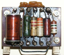
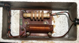
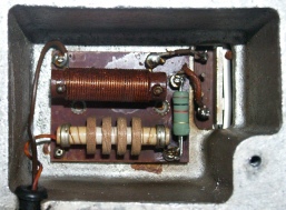
Two views of the bent board in the 100KHz 3rd IF with the burned out resistor
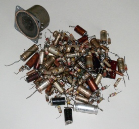
However, the receiver was still lacking sensitivity and any audio resolved was very distorted. It was also clear that the AGC circuit didn’t work either. Speak to anyone with experience in old valve equipment and the first thing they will tell you is ‘re-cap' it. That is, replace any electrolytic and tubular capacitors. Over the years, the old ones dry out or leak wax. Either way, they end up being high value resistors rather than capacitors. This can have detrimental effects on system gain and AGC circuits in particular. This in mind, I began to examine the tubular capacitors in the AGC circuit. Several were reading as little as a few megohms and were duly replaced. However, following the path of the AGC voltage back from the detector was not easy and I soon ‘lost’ it. I had to conclude that what I had did not conform to the circuit diagram. (In hind-sight, I was confusing it with the RA17L) The circuit diagram was definitely that of an RA17 and clearly not for the RA17L. Some more detective work turned up a series of EMERs (Electrical and Mechanical Equipment Regulations) on the Royal Signals website and one of which yielded a circuit diagram specific to early RA17s which sported a different front-end arrangement and similarly simpler AGC circuit. (Again, I had yet to grasp the difference between the RA17L and RA17s). The reason why I ‘lost’ the AGC path was because I had traced it as far as it went, replacing duff capacitors along the way. Sensitivity was still low and the audio still distorted. It was at this point that I made the decision to completely refurbish the receiver. Having seen the horrors that lay inside the 2nd VFO I decided to start with that unit. Also one of the EMERs contained a list of all the recommended modifications to be applied to the RA17, one of which centred on modification to the 2nd VFO.
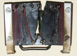
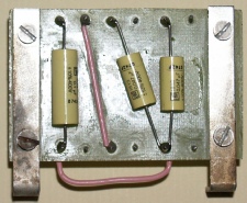
 However, I did not expect this (below). Such had been the heat from the wire-wound resistor that the paxolin board had literally turned to charcoal . . . Woops!
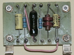
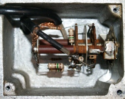
 No problem! A sheet of plain fibre-glass board and some double-sided PCB pins, and half an hour later I had a new board. Note that the 33K resistor has been replaced with an RF choke, in line with recommendations in the EMER. ( See Note below) This increases the volts on the Anode of V12. The wire-wound resistor was retained since it had not altered in value.
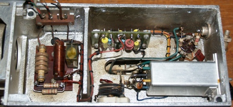
Horrors in the 2nd VFO
2nd VFO nasties but worse to come!
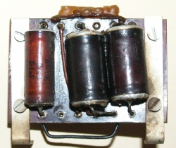
Once you get the 2nd VFO out, it is in fact one of the easier units to work on. The vertically mounted tag-board can be removed quite easily. Personal experience told me to expect resistors that have been stressed to be in excess of 10% high with some being as much as 50% high. Looking at the amount of wax that had pooled at the bottom edge of the board and the exceedingly grotty state of the three capacitors, I was expecting to find some seriously out of spec components. I was not disappointed, although Interestingly, the capacitors were not as bad as expected but one of the carbon resistors was 50% high in value.
No problem! A sheet of plain fibre-glass board and some double-sided PCB pins, and half an hour later I had a new board. Note that the 33K resistor has been replaced with an RF choke, in line with recommendations in the EMER. ( See Note below) This increases the volts on the Anode of V12. The wire-wound resistor was retained since it had not altered in value.
Note: Do NOT do this unless you are working on an RA17L or later. I have since put the 33K resistor back.
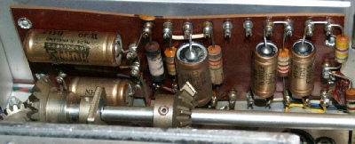
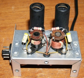
I planned to attack the 1st VFO next, but to gain access to it and in order to remove it, I first had to remove the calibrator, which I suspected was out of alignment. Instead of one well-defined zero-beat every 100KHz I was hearing three! Thus it followed that I should probably ‘do’ the Calibrator next. This definitely is the easiest of all the modules to work on. As can be seen from the photographs, I have not really standardised on replacement components, choosing instead to use those that were at hand. Note for instance the large 1M resistor and three different types of capacitor. Following refurbishment, the calibrator was easily realigned and has worked flawlessly ever since.
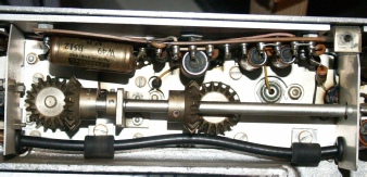
 1st VFO Unit, after
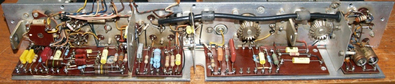 100KHz Tag-Boards complete with only the buffer amplifier remaining ... (far right)
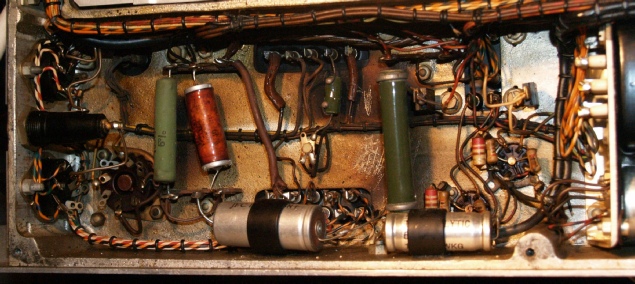
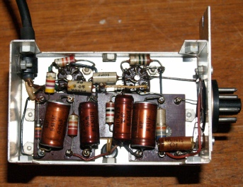
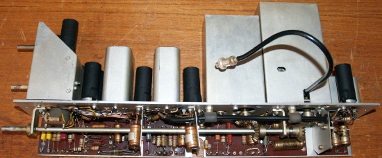
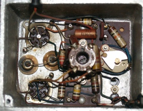
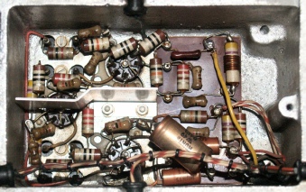
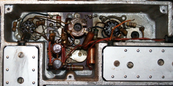 2nd Mixer and 37.5MHz Amplifier, before
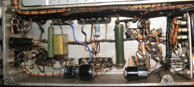
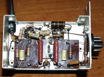
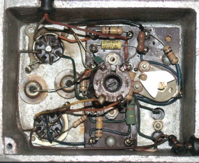
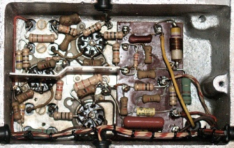
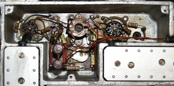 2nd Mixer and 37.5MHz Amplifier, after
These two circuits more or less form the heart of the Wadley Loop and are a mix of tag-board and point-to-point construction. As can be seen in the photograph on the left there was a considerable build up of grime on the two output connectors.
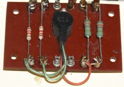
It is worth noting that Racal paid close attention to include appropriate filtering on the HT and heater lines. This was done per unit. The photograph on the left is that pertaining to the Harmonic Mixer/Amplifier. The photograph on the right is the network associated with the 1st VFO. Note that here, as in the 2nd VFO, the 470R resistor (R55) has been replaced with two 1K resistors in parallel.
 Even though the resistors in the input attenuator are unlikely to go too far out of spec., I went ahead and replaced them anyway. The photograph on the right is the meter rectifier. This is a very early solid-state rectifier from an age when valve rectifiers were still commonly used. As a consequence, the manual refers to this curious device as a metal rectifier, which I suppose is inherently accurate too.
 Gone, but not forgotten
In conclusion, this has been a very worthwhile exercise during which time I have learned a lot about the RA17. The receiver itself is a joy to operate. It does require about 30 minutes to warm up and stabilise. Despite the drift canceling nature of the Wadley Loop, the receiver still drifts a little during the first 30 minutes from switch-on. This is due to the 2nd VFO (2.1MHz to 3.1MHz) which is 'outside' the loop and free-running. Thus it is adviseable to leave it 30 minutes, after which time the drift is negligible. For a 50 year old receiver it is really quite astonishing how accurate and stable it is, considering that everything is achieved with just 22 valves (not counting the rectifier). You would be pushed to accomplish such performance with just 22 transistors! Even this MK1 version will give many a modern receiver a good run for it’s money.
Links:
Various Racal or RA17-related sites.
Keith’s Vintage Racal Enthusiasts Site ... This site does not look like it has been updated for several years BUT contains a vast amount of information relating to many pieces of vintage Racal kit.
N3FRQ’s RA17 page ... Provides some background to the RA17 as well as an easy to read description of how it works.
The Blog which inspired this project ... Peter Holtham’s RA117 restoration.
G3NYH’s RA17 related page.
The Racal Shack of Henk PA8PDP.
Sources of Manuals etc.
ww.royalsignals.org.uk ... A superb source of vintage manuals.
The VMARS Archive ... The Vintage and Military Amateur Radio Society.
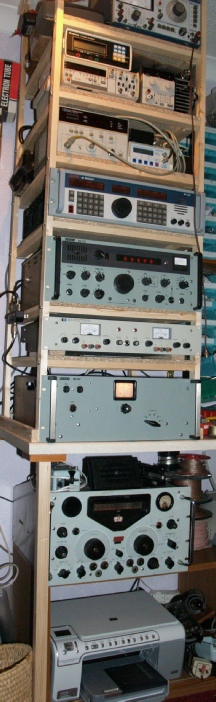
The RA17 sits below the bench since there isn’t actually any room on top. The MA197C is employed in the function for which it was designed and serves to protect the RA17, RA1772 and RA3701 from possible RF damage from the shack (off picture to left).
 Another photograph of my MK1,
this time with the knobs in the right place.
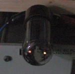
It proved somewhat tricky getting a good photograph of the low output heater filament without compromise, hence the dim shot on the left. Any more exposure would have rendered the two filaments over-exposed and thus indistinguishable. As can clearly be seen, the filament on the left is unmistakably dimmer.
The photograph on the right shows the refurbished 2nd VFO. Note the adjacent filter board. In line with recommended instructions, the 470R resistor has been replaced with two 1K resistors in parallel. The original intent is to reduce the amount of heating incurred by the original half-watt resistors. I should add here that nowhere in my refurbishment did I use anything less than 0.75W resistors and in most cases 1W resistors were used. I re-installed the unit and was delighted to find that the receiver sensitivity was vastly improved. The audio however was still rubbish. Obviously still something wrong somewhere ... Hmm.
Barbeque in the PSU
PSU and Audio Stages before
PSU and Audio Stages after
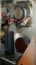
Maybe I should have set about the PSU and Audio Stage compartment first for the simple reason that if the PSU has a fault in it, then it follows that everything else is going to suffer. So in my quest to resolve the terrible sounding audio, I turned my attention to the exceedingly grotty looking PSU compartment which, I have to admit, looked like it had been used as a barbeque! The recommendation in the EMER is to ‘up’ the power rating of the large resistor just right of centre (R119A, 10K, 10W) which dissipates just over 10W when the receiver is set in ‘Stand-By’ mode. I never leave the RA17 in that mode so I opted to leave it be in the mean time. Most of the damage appeared to have been caused by over-cooking of the small vitreous enamel wire-wound resistor in the centre (R136, 47R, 3W). I replaced it with a 4W carbon resistor which so far has not exhibited ANY signs of stress or heating. The chassis cleaned up remarkably well simply by giving it a scrub with ‘Flux-Off’. The two electrolytics were duly replaced as were all the carbon composite resistors.
So far I have not replaced the main PSU smoothing capacitors ... Initially because I was not able to obtain a 32uF+32uF capacitor. Instead I have a couple of 47uF capacitors that I am prepared to glue together . However, the integrity of the HT supply is good (no hum) so I will defer replacement for the moment. I switched the RA17 back on fully expecting the audio to now be free from distortion ... But sadly it was still as distorted as ever. Then I hit on the idea of connecting an external loudspeaker to one of the sets of rear- panel output terminals. To my astonishment, the audio on this ‘other’ loudspeaker was completely free from distortion. A quick rummage through my box of small loudspeakers yielded one that was almost exactly the right size. I have no idea where it came from. The mounting holes needed to have rivets drilled out and then filed very slightly in order to fit it. Hey-Presto! ... distorted audio problem resolved! I can only surmise that corrosion may have built up between the pole pieces in the original Goodmans unit and was interfering with the travel of the voice-coil.
The Calibrator
Calibrator inside, before
Calibrator inside, after
I planned to attack the 1st VFO next, but to gain access to it and in order to remove it, I first had to remove the calibrator, which I suspected was out of alignment. Instead of one well-defined zero-beat every 100KHz I was hearing three! Thus it followed that I should probably ‘do’ the Calibrator next. This definitely is the easiest of all the modules to work on. As can be seen from the photographs, I have not really standardised on replacement components, choosing instead to use those that were at hand. Note for instance the large 1M resistor and three different types of capacitor. Following refurbishment, the calibrator was easily realigned and has worked flawlessly ever since.
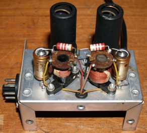
Calibrator tuning coils, before
Calibrator tuning coils, after
The 1st VFO Module
1st VFO Unit, before
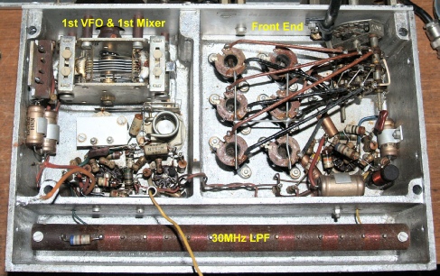
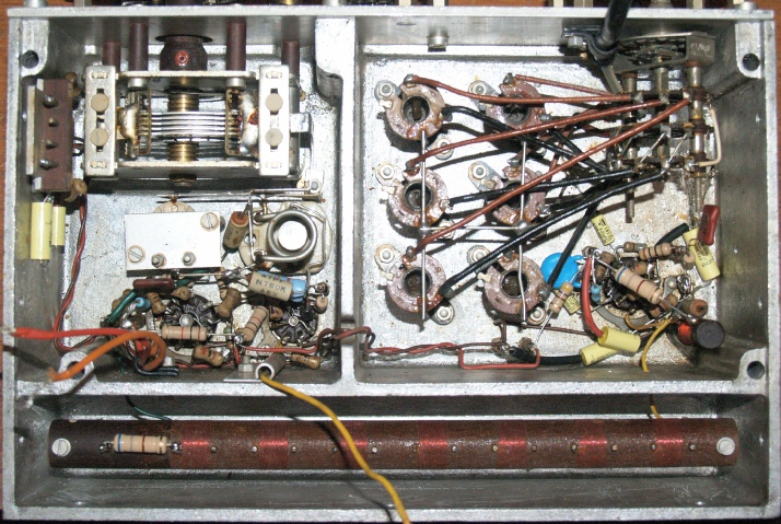
The unit commonly referred to as the 1st VFO actually encompasses the Front-End with Preselector, 1st VFO, 1st Mixer and the 30MHz Low-Pass-Filter. Since this particular RA17 is a MK1, the Front-End Preselector circuitry is exceptionally simple. However the lack of any tag-boards renders this an awkward unit to work on. Where components are simply strung between valve base pins for instance, you have to work out the order in which they were originally connected in order to remove them without breaking anything. I found that the easiest way to accomplish this was to cut the lead off a resistor for instance, thus allowing each end to be more easily ‘unwound’. When fitting the new components I was careful to ensure that wherever possible, they were positioned as close as possible to the original parts, maintaining continuity with the layout photographs in the manual.
1st VFO Unit, after
100KHz 3rd IF
100KHz Unit partially refurbished
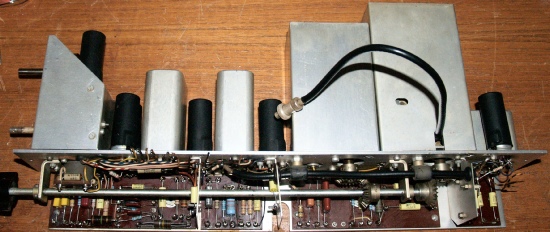
The 100KHz unit (3rd IF) is the largest of all the removable units, forming the complete left side of the chassis and containing the 100KHz amplifier stages (V14 & V16), the 100KHz rear panel buffer amplifier (V17), AGC and detector circuitry (V18 & V21) and BFO (V19) as well as the Crystal Filter module and the L-C Filter module. This huge unit was already partially refurbished when replacing a burned out resistor and investigating the AGC circuit operation. The spindle can be removed for easy access to the tag-boards, see below.
100KHz Tag-Boards complete with only the buffer amplifier remaining ... (far right)
100KHz Unit after refurbishement
It is easy to overlook those capacitors and resistors hiding away within the metal cans. The two filter units are no exception, there being a couple of resistors within the L-C Filter unit which can be reached with minimum disturbance. However those within the Crystal filter are not so easy to reach. I decided to leave them since experience was already showing that only those resistors carrying significant current were likely to be out of spec. The BFO was not forgotten and proved a fiddly little beast to work on.
2nd Mixer
2nd Mixer and 37.5MHz Amplifier, before
We now turn our attention to the various circuits lurking in the die-cast labyrinth that is the chassis. This is the 2nd Mixer and 37.5MHz Amplifier which is deceptively tricky to work on. I had already started to remove a few components before I remembered to take the above photograph, hence the loose wire and missing resistor. It was on completion of this circuit that I had my second ‘Oops!’ of the project. (The first being the shattered tag-board in the 2nd VFO). This time round it was a bit more serious and produced some smoke! After replacing all the Rs and Cs I replaced the cover and switched on the RX ... Nothing. I removed the cover to the 2nd mixer and a cloud of smoke greeted me ... Not good. The 1K resistor (R66) at the bottom of the photograph was completely fried. The cold end of the resistor was intermittently shorting to ground which made tracing the fault particularly frustrating. The culprit turned out to be minute flakes of solder that had infiltrated the vanes of C108 in the 37.5MHz amplifier. Throughout this project I have deliberately avoided disturbing any tuned circuits. A squint at C108 showed that the movable vanes were not positioned exactly mid-way (vertically) between the static vanes, and unlike in large variable capacitors, there is no adjustment. I rotated the vanes and three tiny shards of solder were ejected. However once the vanes were fully unmeshed and I continued the rotation, they clashed due to the imperfect construction. I moved the vanes back to roughly where they had been set. If I moved them too far, they touched again, so I backed off a bit and left C108 at that. Fortunately the circuit was easily retuned by way of the adjacent L50 which is in parallel with C108. I have had no further problem with this circuit, although if I get the opportunity I will replace C108 if and when I can lay my hands on a better variable capacitor.
2nd Mixer and 37.5MHz Amplifier, after
1MHz Osc. and Harmonic mixer
Crystal Oscillator, before
These two circuits more or less form the heart of the Wadley Loop and are a mix of tag-board and point-to-point construction. As can be seen in the photograph on the left there was a considerable build up of grime on the two output connectors.
Crystal Oscillator, after
The Harmonic Amplifier is fairly component intensive but was easier to refurbish than expected. The large tubular capacitor was duly replaced with a smaller type (brown C) and I was able to mount it more neatly, albiet not as per the component layout. I decided to leave the 470R resistor (R18) with L20 around it.
Harmonic Mixer and 37.5MHz Amps, before
Harmonic Mixer and 37.5MHz Amps, after
Miscellaneous other bits
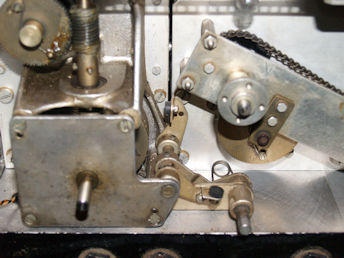
Now this one had me scratching my head. I can’t remember where I read it, but I already knew that locking of the main tuning dials on the RA17 series was achieved by way of tiny brake pads. It wasn’t really a surprise either to find that they were a tad worn too. One of the EMERs describes how these stick on pads can become loose and fall off if the dial is operated with the brake applied, and thus describes the procedure for fitting bolt-on rubber brake pads. I fully expected to read that the levers would require drilling to take the 6BA screws. But no, the holes are already there! One has to ask, why on earth were inferior stick-on pads fitted in preference to the bolt-on variety? Quite by accident, I found a source of rubber dial brakes on Ebay!
Conclusions
Looking much better than it did when I picked it up. There is still a slight staining of the Light Admiralty Grey paintwork which I am prepared to put up with since I fear that more attempts to further clean the panel will only remove the already fragile (in places) lettering.
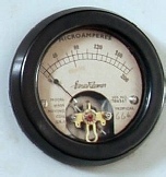
Note also that the meter movement has been changed from the original which was open-circuit. Just by shaking it I could tell that one of the hair-springs was off, although I couldn’t tell whether it was the top or bottom one ... and in any case, trying to re-attach it would be too difficult on such a small movement. (I’ve repaired a couple of AVO movements in the past). As luck would have it, I uncovered a 200uA meter in my junk box. Comparing the two movements size-wise, they were almost identical. Only slight cosmetic surgery with a hack-saw and needle file was required inside the original housing to allow it to take the new movement. The meter switch was also broken internally. A replacement and a couple of spares were obtained via Ebay.
As mentioned earlier, the receiver performance was checked periodically throughout the refurbishment. One thing that was very evident was that as components were replaced, the overall noise figure consistently dropped. At one point I was convinced that something was wrong. Only then did I realise that I hadn’t re-connected the antenna, it was so quiet. I have replaced both the CV4025 double diodes and all three of the CV3998s with noticeable improvement. Interestingly, one of the CV3998s that I replaced (V9) was white! ... indicating a slow leak ... but at the time of replacement it was still operating ... Hmmm?
As mentioned earlier, the receiver performance was checked periodically throughout the refurbishment. One thing that was very evident was that as components were replaced, the overall noise figure consistently dropped. At one point I was convinced that something was wrong. Only then did I realise that I hadn’t re-connected the antenna, it was so quiet. I have replaced both the CV4025 double diodes and all three of the CV3998s with noticeable improvement. Interestingly, one of the CV3998s that I replaced (V9) was white! ... indicating a slow leak ... but at the time of replacement it was still operating ... Hmmm?
Gone, but not forgotten
Some RA17 Links etc.
The Rack, early 2009
In conclusion, this has been a very worthwhile exercise during which time I have learned a lot about the RA17. The receiver itself is a joy to operate. It does require about 30 minutes to warm up and stabilise. Despite the drift canceling nature of the Wadley Loop, the receiver still drifts a little during the first 30 minutes from switch-on. This is due to the 2nd VFO (2.1MHz to 3.1MHz) which is 'outside' the loop and free-running. Thus it is adviseable to leave it 30 minutes, after which time the drift is negligible. For a 50 year old receiver it is really quite astonishing how accurate and stable it is, considering that everything is achieved with just 22 valves (not counting the rectifier). You would be pushed to accomplish such performance with just 22 transistors! Even this MK1 version will give many a modern receiver a good run for it’s money.
Links:
Various Racal or RA17-related sites.
Keith’s Vintage Racal Enthusiasts Site ... This site does not look like it has been updated for several years BUT contains a vast amount of information relating to many pieces of vintage Racal kit.
N3FRQ’s RA17 page ... Provides some background to the RA17 as well as an easy to read description of how it works.
The Blog which inspired this project ... Peter Holtham’s RA117 restoration.
G3NYH’s RA17 related page.
The Racal Shack of Henk PA8PDP.
Sources of Manuals etc.
ww.royalsignals.org.uk ... A superb source of vintage manuals.
The VMARS Archive ... The Vintage and Military Amateur Radio Society.
The RA17 sits below the bench since there isn’t actually any room on top. The MA197C is employed in the function for which it was designed and serves to protect the RA17, RA1772 and RA3701 from possible RF damage from the shack (off picture to left).
I had to laugh the other day. I was almost finished refurbishing the RA17 when I commented to the XYL that I wouldn’t mind taking up restoring old Racal kit as a profession. I was joking. However a couple of days later, a friend who I had not spoken to for some time ‘phoned me about repairing a PC (that’s what I did back in 2009). We got chatting and I commented that I was just about finished restoring the RA17 ... And he said, "How would you like to repair mine for a suitable sum?"
Another photograph of my MK1,this time with the knobs in the right place.
Faulty GZ34
The other day I became aware that something was not right with the RA17. Sensitivity and audio output were down and the AVC (AGC) was not functioning correctly. This condition would spontaneously clear after anything from 30 minutes to several hours. This afternoon I tackled the problem. Maybe I should have set about it clinically, however, after substituting several valves to no avail, I finally measured the HT voltage and found it to be only 80V. Interestingly, setting the main function switch to Stand-By resulted in the HT rising to 250V. Since the RA17 is essentially modular, I thought it would be simply a case of ‘lifting’ appropriate HT wires until the obvious excess loading was removed. However this exercise was inconclusive. Very likely what I should have done was ‘scope’ the HT line ... But I didn’t. Anyway, with all avenues exhausted I finally replaced the GZ34 rectifier with my one and only spare ... BINGO! Actually, looking down on the original GZ34, it was evident that one of the heaters was dimmer than the other. Schematically the GZ34 has a single 5V heater. However, due to its construction it has to have two heaters which are obviously wired in parallel. I did find a data sheet which actually shows it as two parallel heaters. While I can see how one filament might fail outright, I’m not really sure why one might diminish in output. Whatever the reason, this was clearly the cause of the low HT voltage. Looking back at the various faults and seriously cooked bits and pieces that I encountered during the restoration work, it is likely that the excess current incurred had over-stressed the valve to some extent.
The GZ34 is reckoned by many to be the finest general purpose valve rectifiers ever manufactured. A search on Ebay will only highlight this. Those with the small brown base will set you back well over 100GBP! I don’t expect the replacement to fail in a hurry, so I shall shop around for a replacement so that I am not without a spare.
The GZ34 is reckoned by many to be the finest general purpose valve rectifiers ever manufactured. A search on Ebay will only highlight this. Those with the small brown base will set you back well over 100GBP! I don’t expect the replacement to fail in a hurry, so I shall shop around for a replacement so that I am not without a spare.
It proved somewhat tricky getting a good photograph of the low output heater filament without compromise, hence the dim shot on the left. Any more exposure would have rendered the two filaments over-exposed and thus indistinguishable. As can clearly be seen, the filament on the left is unmistakably dimmer.
Thoughts on SSB reception:
A search of the internet will yield more than a few articles declaring that the RA17’s detector circuitry is fine for AM reception but lousy for SSB. Consequentially there are a couple of designs offering modifications to the detector circuitry. Some would have you believe that the RA17 was never intended for SSB reception, hence the need for the RA63. This is not necessarily the case. Interestingly I have absolutely NO problems resolving SSB signals, strong or weak. My theory is that if you are using an RA17 full of leaky capacitors and out of spec. resistors, don’t expect it to work as well as it did when it left the factory in 1958. With this in mind it is worth noting that since the RA17L and subsequent models sported a different front end and an extended AGC line, these models are more likely to exhibit SSB reception issues since the AGC circuitry is particularly at risk regards ‘leaky’ capacitors.
A search of the internet will yield more than a few articles declaring that the RA17’s detector circuitry is fine for AM reception but lousy for SSB. Consequentially there are a couple of designs offering modifications to the detector circuitry. Some would have you believe that the RA17 was never intended for SSB reception, hence the need for the RA63. This is not necessarily the case. Interestingly I have absolutely NO problems resolving SSB signals, strong or weak. My theory is that if you are using an RA17 full of leaky capacitors and out of spec. resistors, don’t expect it to work as well as it did when it left the factory in 1958. With this in mind it is worth noting that since the RA17L and subsequent models sported a different front end and an extended AGC line, these models are more likely to exhibit SSB reception issues since the AGC circuitry is particularly at risk regards ‘leaky’ capacitors.