HP 5065A Rubidium Vapour Frequency Standard
9 minute read
This post is part of the series 'Test Equipment':
 First of all ...
This isn't mine. Much as I'd like to own one, I don't really need one, as I have my Rapco 1804 P9 GPS Precision Frequency Source. However a few weeks ago I was asked if I might have a look at a faulty HP5065A Rubidium Vapour Frequency Standard which had stopped working. And not being one to turn down a challenge, I said 'OK'.
Where does a Rubidium Frequency Standard actually sit in the grand scheme of Frequency Standards anyway? Surprisingly, such things are only one step up from the humble crystal oscillator ... and by that we're probably talking about OCXOs (Oven-Controlled Crystal Oscillators). Cesium-Beam-controlled frequency standards would be on the next level up ... offering better stability and greater immunity from environmental variations, all at a much higher price. Finally there is the Hydrogen Maser which is the most stable oscillator known ... heavy and VERY expensive!
Interestingly, GPS-linked frequency-standards indirectly benefit from Cesium-based frequency-sources on orbiting satellites, which is likely the reason why they can offer remarkably stable frequencies. For example ...
The long term drift rate of the HP5065A's 5MHz output is given as +/- 1 x 10E11 per month. Typically, my Rapco system offers +/- 5 x 10E11 over the same period ... and it offers five independently buffered 10MHz outputs.
So, from my perspective the Rapco wins, as I can directly drive my two GPS-locked microwave transverters and my Adret synthesiser and still have two spare outputs.
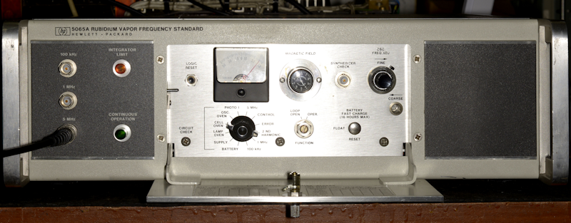
But, back to the faulty 5065A. All I was told was that operation had been intermittent, before finally failing. This is a late-model version of the 5065A with a serial number prefix of 2816A. Immediately, this presents a problem if, like me, your 5065A came sans-manual. The problem is that the only manual available for free download online is dated 1979 and the one I had on the bench was very obviously manufactured after 1988. Anyway ... Behind the fold-down door there is what looks like a mish-mash of random controls ... no two are alike! The one which looks like a clock is actually just a fancy vernier control. I was interested in the 'Circuit Check' Switch which with the meter, gives an indication of the health of the 5065A's 'vitals' so to speak.
There are apparently three options available for the 5065A. Option 1 is a Time Standard. Option 2 is a Standby Power Supply (Battery with charger), and Option 3 is Options 1 & 2 together ... hmmm? This one was 'optionless'. Thus there was no reading on the meter when 'Battery' was selected. When set to 'Supply', the meter was off the scale ... not a good sign. Clearly the other switch positions were all indicative of a total system failure. There was a 5MHz signal at the front and rear panels but it was only about 50mV p-p when it should have been greater than 1V rms into 50-ohms.
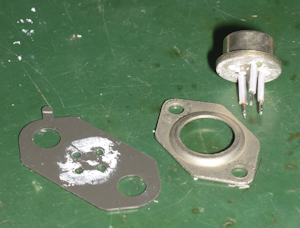
Straight away it was obvious that the pass-transistor in the very simple power-supply was permanently passing the bulk DC. In keeping with HP's propensity for 'company-coding' many components, the transistor in question was labelled 1854-0020. What on earth is that? There are several lists available on-line pertaining to HP's part numbers ... only one of which lists part number 1854-0020, and even then all it tells me is that it cost $4.00 ... not a lot of help! So I simply replaced it with a 2SC1173 TO-220 form-factor transistor.
With the pass-transistor replaced and the +20V rail now restored, I was hoping for some life in the beast, except the 5MHz output was still pitifully low. So I now turned my attention to the Turn-On Procedure which I found on page 3-3 in the manual. However, with this being a faulty 5065A, I was not surprised that the procedure did NOT result in a working frequency standard. Step 7 refers to the Circuit Check Switch and associated meter readings listed in Table 3-1, which incidentally is found two pages previous on page 3-1. OK, but what if some of the readings are wildly out? In my case, all three of the Oven readings were off the scale ... is that a problem? One could be forgiven for expecting a detailed explanation, but nope! For this, you have to 'fast-forward' to Table 5-3 on page 5-8 for that information ... where it states 'NOTE: If either reading is full scale, remove power and allow oven to cool; then effect repairs. CONTINUED OPERATION WITH METER AT FULL SCALE (AFTER INITIAL WARMUP) CAN CAUSE DAMAGE TO THE RVFR ASSY.'
To be fair, the key words there are 'after initial warmup' and in another column it is suggested that 'about 1 hour' might be a reasonable time. So I left it running, hoping that the ovens in the RVFR were not being stressed. After about 45 minutes all three oven readings were thankfully within limits. But the 5MHz output was still a measly 50mV p-p. In fact all the Circuit Check positions clock-wise from and including the 5MHz position were either zero or out of spec. Here, Table 5-3 was again somewhat unclear with respect to the 5MHz signal. It does suggest a series of places to check for a signal in the event of there being no output signal. But I had a signal ... albeit very small. It was very evident that the A10 Oscillator module itself was at fault.
The image above shows the location of the 5MHz OCXO. It also shows it to be a sealed unit, a fact confirmed by figure 8-20 on page 8-53 of the manual which shows that the A10 Oscillator Assembly consists of four interconnected assemblies contained within a double-insulated sealed enclosure and that the oven runs from 115V AC. Nothing like the A10 5MHz OCXO that I was looking at.
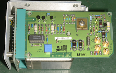
The photograph on the left shows the A10 Oscillator module removed from the chassis. Unfortunately, since the module shown in the manual is a sealed unit, there is no circuit diagram, so I was going to have to 'wing it' here. Powering it up was easy ... +24V, +20V and +15V ... although the 15V line was probably unnecessary. I was relieved to see that the oven and the oscillator were functioning correctly. The signal from the oscillator comes onto the board in the photograph at the top left. the 14-pin DIL chip is some sort of Dual D-Type Flip-Flop and HP's part number translates as type 4345 which I could not find any data on. However I did find an HP manual for another piece of test equipment which mercifully gave me the pin-out. Only one half of this IC is used to 'square off' the incoming signal. The three transistors at the top form some sort of level control ... which I found to be non operational. The fault turned out to be an open-circuit 500R trimmer potentiometer. I didn't have a suitable replacement, but I fitted a 1K trimmer of similar form-factor which did the trick. I was now getting close to 3V p-p at J3 on the module.
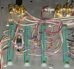
The photograph on the right shows the repaired A10 module refitted on the chassis. All I had to then do was switch the 5065A back on and wait. The 5MHz oscillator signal was within spec., but the 2nd Harmonic reading was very low, just under 10 when ideally it should be between 20 and 40. The manual states that as the RVFR ages the level of 2nd Harmonic will drop. A simple procedure for compensating for this is in section 5-24 on page 5-12 in the manual. However the A3 module has obviously been re-designed since the 1979 manual was published to the extent that A3R3 and A3R11 are now A3R29 and A3R54 (see below).
With A8TP3 and A8TP2 connected to Channels A and B respectively on my HP 1745A it was a simple matter of adjusting A3R29 and A3R54 to achieve an image as in Figure 5-10 on page 5-12 of the manual. Then a final tweak of A3R54 to settle the 2nd Harmonic reading on 30 on the meter. Other adjustments setting the oscillator Coarse and Fine controls and thus the 'Control' reading on the meter in section 5-7 on page 5-1 are simple to follow.
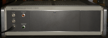
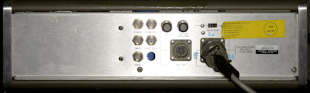 Finally; above left, the front of the 5065A with the door on the front panel folded up and locked in position. On the right, the rear of the 5065A showing the non-IEC screw-on mains cord. Before the advent of the IEC standard, early HP equipment came with a NEMA type connector on the rear panel for the mains cord. So why does the 5065A come with a mil-spec screw on connector? An educated guess would be that as both the NEMA connector and the IEC connector can inadvertently be pulled out; and accidentally switching off your frequency standard is very likely to upset someone ... a screw-on mains lead was probably considered a good idea.
- Test Equipment for Test Equipment
- Two Adret Signal Generators
- Hewlett Packard HP1740A Repair
- HP 5065A Rubidium Vapour Frequency Standard
July 2024
This isn't mine. Much as I'd like to own one, I don't really need one, as I have my Rapco 1804 P9 GPS Precision Frequency Source. However a few weeks ago I was asked if I might have a look at a faulty HP5065A Rubidium Vapour Frequency Standard which had stopped working. And not being one to turn down a challenge, I said 'OK'.
Where does a Rubidium Frequency Standard actually sit in the grand scheme of Frequency Standards anyway? Surprisingly, such things are only one step up from the humble crystal oscillator ... and by that we're probably talking about OCXOs (Oven-Controlled Crystal Oscillators). Cesium-Beam-controlled frequency standards would be on the next level up ... offering better stability and greater immunity from environmental variations, all at a much higher price. Finally there is the Hydrogen Maser which is the most stable oscillator known ... heavy and VERY expensive!
Interestingly, GPS-linked frequency-standards indirectly benefit from Cesium-based frequency-sources on orbiting satellites, which is likely the reason why they can offer remarkably stable frequencies. For example ...
The long term drift rate of the HP5065A's 5MHz output is given as +/- 1 x 10E11 per month. Typically, my Rapco system offers +/- 5 x 10E11 over the same period ... and it offers five independently buffered 10MHz outputs.
So, from my perspective the Rapco wins, as I can directly drive my two GPS-locked microwave transverters and my Adret synthesiser and still have two spare outputs.
But, back to the faulty 5065A. All I was told was that operation had been intermittent, before finally failing. This is a late-model version of the 5065A with a serial number prefix of 2816A. Immediately, this presents a problem if, like me, your 5065A came sans-manual. The problem is that the only manual available for free download online is dated 1979 and the one I had on the bench was very obviously manufactured after 1988. Anyway ... Behind the fold-down door there is what looks like a mish-mash of random controls ... no two are alike! The one which looks like a clock is actually just a fancy vernier control. I was interested in the 'Circuit Check' Switch which with the meter, gives an indication of the health of the 5065A's 'vitals' so to speak.
There are apparently three options available for the 5065A. Option 1 is a Time Standard. Option 2 is a Standby Power Supply (Battery with charger), and Option 3 is Options 1 & 2 together ... hmmm? This one was 'optionless'. Thus there was no reading on the meter when 'Battery' was selected. When set to 'Supply', the meter was off the scale ... not a good sign. Clearly the other switch positions were all indicative of a total system failure. There was a 5MHz signal at the front and rear panels but it was only about 50mV p-p when it should have been greater than 1V rms into 50-ohms.
Very odd pass-transistor.
Straight away it was obvious that the pass-transistor in the very simple power-supply was permanently passing the bulk DC. In keeping with HP's propensity for 'company-coding' many components, the transistor in question was labelled 1854-0020. What on earth is that? There are several lists available on-line pertaining to HP's part numbers ... only one of which lists part number 1854-0020, and even then all it tells me is that it cost $4.00 ... not a lot of help! So I simply replaced it with a 2SC1173 TO-220 form-factor transistor.
Replacement Transistor (2SC1173).
With the pass-transistor replaced and the +20V rail now restored, I was hoping for some life in the beast, except the 5MHz output was still pitifully low. So I now turned my attention to the Turn-On Procedure which I found on page 3-3 in the manual. However, with this being a faulty 5065A, I was not surprised that the procedure did NOT result in a working frequency standard. Step 7 refers to the Circuit Check Switch and associated meter readings listed in Table 3-1, which incidentally is found two pages previous on page 3-1. OK, but what if some of the readings are wildly out? In my case, all three of the Oven readings were off the scale ... is that a problem? One could be forgiven for expecting a detailed explanation, but nope! For this, you have to 'fast-forward' to Table 5-3 on page 5-8 for that information ... where it states 'NOTE: If either reading is full scale, remove power and allow oven to cool; then effect repairs. CONTINUED OPERATION WITH METER AT FULL SCALE (AFTER INITIAL WARMUP) CAN CAUSE DAMAGE TO THE RVFR ASSY.'
To be fair, the key words there are 'after initial warmup' and in another column it is suggested that 'about 1 hour' might be a reasonable time. So I left it running, hoping that the ovens in the RVFR were not being stressed. After about 45 minutes all three oven readings were thankfully within limits. But the 5MHz output was still a measly 50mV p-p. In fact all the Circuit Check positions clock-wise from and including the 5MHz position were either zero or out of spec. Here, Table 5-3 was again somewhat unclear with respect to the 5MHz signal. It does suggest a series of places to check for a signal in the event of there being no output signal. But I had a signal ... albeit very small. It was very evident that the A10 Oscillator module itself was at fault.
Now, I previously said that the only manual available online is one dated 1979.
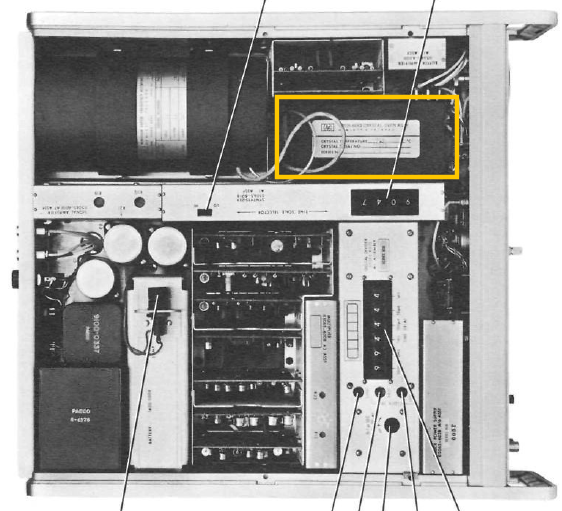
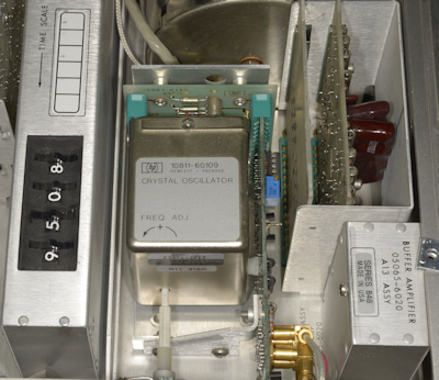
Original 5MHz OCXO outlined in yellow.
The image above shows the location of the 5MHz OCXO. It also shows it to be a sealed unit, a fact confirmed by figure 8-20 on page 8-53 of the manual which shows that the A10 Oscillator Assembly consists of four interconnected assemblies contained within a double-insulated sealed enclosure and that the oven runs from 115V AC. Nothing like the A10 5MHz OCXO that I was looking at.
More accessible OCXO.
The photograph on the left shows the A10 Oscillator module removed from the chassis. Unfortunately, since the module shown in the manual is a sealed unit, there is no circuit diagram, so I was going to have to 'wing it' here. Powering it up was easy ... +24V, +20V and +15V ... although the 15V line was probably unnecessary. I was relieved to see that the oven and the oscillator were functioning correctly. The signal from the oscillator comes onto the board in the photograph at the top left. the 14-pin DIL chip is some sort of Dual D-Type Flip-Flop and HP's part number translates as type 4345 which I could not find any data on. However I did find an HP manual for another piece of test equipment which mercifully gave me the pin-out. Only one half of this IC is used to 'square off' the incoming signal. The three transistors at the top form some sort of level control ... which I found to be non operational. The fault turned out to be an open-circuit 500R trimmer potentiometer. I didn't have a suitable replacement, but I fitted a 1K trimmer of similar form-factor which did the trick. I was now getting close to 3V p-p at J3 on the module.
Refitted A10 module.
The photograph on the right shows the repaired A10 module refitted on the chassis. All I had to then do was switch the 5065A back on and wait. The 5MHz oscillator signal was within spec., but the 2nd Harmonic reading was very low, just under 10 when ideally it should be between 20 and 40. The manual states that as the RVFR ages the level of 2nd Harmonic will drop. A simple procedure for compensating for this is in section 5-24 on page 5-12 in the manual. However the A3 module has obviously been re-designed since the 1979 manual was published to the extent that A3R3 and A3R11 are now A3R29 and A3R54 (see below).
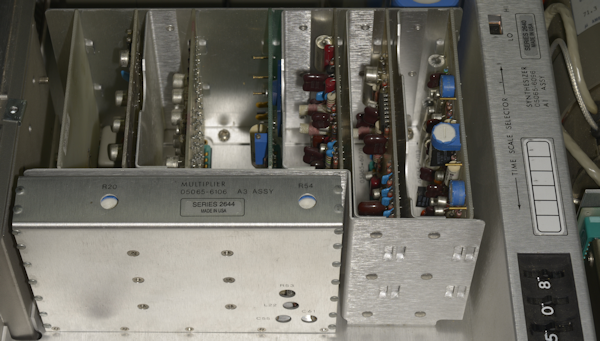
Revised A3 module.
With A8TP3 and A8TP2 connected to Channels A and B respectively on my HP 1745A it was a simple matter of adjusting A3R29 and A3R54 to achieve an image as in Figure 5-10 on page 5-12 of the manual. Then a final tweak of A3R54 to settle the 2nd Harmonic reading on 30 on the meter. Other adjustments setting the oscillator Coarse and Fine controls and thus the 'Control' reading on the meter in section 5-7 on page 5-1 are simple to follow.