300W HF Amplifier
10 minute read
We need more power!
In March of 2001, I embraced the idea that I should endeavour to run more power on HF. My confirmed DXCC total was by then well over 200, and those entities left un-worked tended to be somewhat rare, and on many people’s ‘most wanted’ lists. The problem there is that when a rare entity comes ‘on-air’, the whole world and his brother pounce on him. I needed an amplifier. One thing I had to be mindful of was the fact that my ATU is only rated at 300W. Initially I hadn’t considered building my own amplifier, and I began searching for ‘off the shelf’ proprietary kit . . . . . without success. It appeared that if I was going to buy one, I would have to invest in one capable of developing 800W at just over 1 UK pound per Watt! A ‘trawl’ of the Internet yielded roughly the same result. I was going to have to build my own!
A browse through the Motorola RF Devices data book reintroduced me to Helge Granberg’s designs and in particular, Application Note AN758, which describes a 1.2KW HF Linear. This design employs a quad of 300W Push-Pull amplifiers in it’s final stage, combined to comfortably deliver just over 1KW. This particular design runs from a 50V supply, which might be looked on as being difficult to obtain, particularly when the current drawn by one 300W stage alone can be in the region of 14 amps. 50V power supplies are simply not readily available, particularly at that sort of rating. A similar amplifier running from a 28V supply would require around 20A and to develop that sort of power from a 13.8V supply would require an input current in the region of 50A!
I was going to have to build my own power supply anyway, so I figured that I might as well go for the 50V option. In June 1986, John Matthews, G3WZT published an article in RadCom describing a single stage linear amplifier for 50MHz. This article also details a very robust 50V high current PSU complete with ‘soft-start’, over-current and over-voltage protection. I found that power darlingtons are essential as pass transistors in this design and I was most impressed when I had smoke pouring off my power rheostat while the output voltage remained ‘rock steady’.
The January 1992 issue of RadCom described a 150W HF linear amplifier by Mike Grierson, G3TSO. This used another of Helge Granberg’s designs, with the actual amplifier being supplied in kit-form by Communications Concepts of Ohio, U.S.A. A quick e-mail to CCI confirmed that they were able to supply the AN758 units for a very reasonable price . . . . . and a look at their WebSite confirmed that they could also supply the parts for the necessary output filters. I ended up also getting the massive heat sink from them too. I decided that this was going to be a ‘quality’ project and set out from the start to design something that not only looked good, but also had one or two features not generally found on ‘home-brew’ kit.
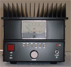
300W Amplifier - Front Panel
Getting the 50V into the box was my first concern. 50V is a high voltage, sufficient to give you a fright if you’re not careful, and more than sufficient to cause expensive damage if the polarity were reversed! I didn’t want a heavy on/off switch on the front panel, but I did want front panel switching. At these high currents it’s tempting to forego any switching and simply wire the power right into the unit. However I came up with a way to combine reverse polarity protection and DC input switching by using a high current relay, a diode and an attractive illuminated switch. When the supply is connected, a small green LED illuminates, indicating that the PSU is on. Pressing the large red button on the front of the amplifier energises the high current relay via a diode, connecting the 50V (48V, actually) to the rest of the circuitry. The diode serves to prevent the relay energising in the event that the polarity is reversed.
Initially, I wasn’t going to have any metering on the amplifier since I already have a VSWR/Power Meter. However in light of the expensive nature of the output devices (a matched pair of MRF429s), I felt it was prudent to include a Collector Current meter.
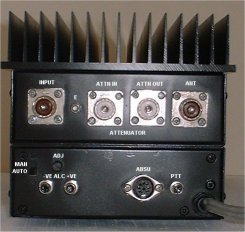
300W Amplifier - Rear Panel
The rear panel, has four rather than the usual two SO-239 sockets. The AN758 typically requires between 15 and 18 watts to drive it to it’s maximum output. The majority of transceivers these days deliver around 100W while a much smaller number will deliver up to 200W and a few others offer 30W or less. Even if the output power can be adjusted by way of a front panel control, it is still very easy to accidentally over-drive the amplifier and send the PA devices into melt-down. So I decided to make provision for an external attenuator which can be omitted and replaced with a length of coax if not required. Phono sockets are provided for PTT input and ALC output and the DIN connector is for interfacing to the Auto Band Selector Unit.
300W Amplifier - Rear Panel
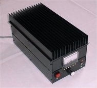
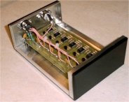
The amplifier is housed in two readily available aluminium boxes, mounted back-to-back. The top unit houses the actual amplifier along with the R.F. Change-Over relays and power detector circuit. The lower unit houses the six, five element Chebyshev filters along with the control circuitry on the back panel and the front panel control board. Right from the start, I had the idea of having the amplifier ‘track’ my IC725 (or any ICOM transceiver). As is clear from the photograph below, space is a premium on the ‘lower deck’, and I didn’t want to use the ‘upper deck’. Therefore it was necessary to build the ‘band switching unit’ as an external unit. This worked out quite well for a number of reasons. Initially, the DIN connector on the rear panel was for direct interfacing with ACC2 on ICOM transceivers, carrying PTT, ALC and Band Voltage.
Lower deck nearing completion
However, for some reason that I have not been able to figure out, the PTT line on ACC2 is not the same line as present on the Phono connector, and as such is not compatible with the amplifier. Abandoning the concept of a single cable interface left me with a redundant connector. Consequently, the DIN connector now handles the Band Switching Interface. There is a switch on the rear panel of the amplifier for switching between Manual Band Switching and Automatic Mode.
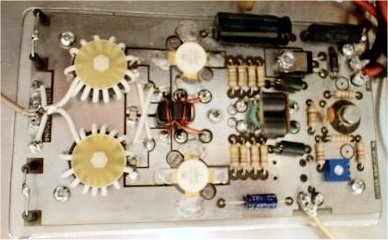
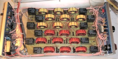
The 300W Amplifier PEC
Pictured right is the actual 300W amplifier PEC. Note the use of coaxial transformers to match the output to 50-ohms. We had a bit of a miss-hap when we first powered it up. It worked first time and developed the power as expected. Then the Collector Current meter 'kicked' and no power after that. To cut a long story short, the uA723 regulator in the Bias supply turned out to be faulty and rather than producing a constant voltage, the output was rising VERY slowly. Consequently the quiescent current in the MRF429s rose excessively until they blew. I wasn't able to convince CCI that they had supplied me with a faulty regulator so I had to fork out for a replacement matched pair of MRF429s and 100 US Dollars plus UK import tax ... OUCH!
This faulty regulator experience left me a tad paranoid, as might be expected! Thus after fitting the replacement uA723 I fitted a pair of silicon diodes in place of the base-emitter junctions of the MRF429s and left the regulator running for at least an hour ... and only when I was satisfied that the quiescent current wasn't going to 'run away' did I fit the new PA devices.
Auto Band Select Unit
Left: My Auto Band Select Unit which I have to admit, is somewhat over-engineered, in that rather than asking ICOM for the band switching voltage tolerances, I worked them out and designed a ‘ladder’ comparator network to perform the selection. I have since discovered a simpler albeit similar design. I have also come across an even more ingenious design using an LED driver array to perform the same task. Subsequently, I have also made a universal version based on a PIC design by Peter Rhodes, G3XJP.
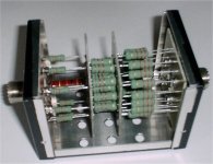
8dB attenuator
Right: Inclusion of the 8dB attenuator allows more control over the level of drive to the amplifier. It might also be said that running the exciter’s output at a higher level, improves the linearity. Although intended for a max input of 100W, giving about 15W into the amplifier, the attenuator has been designed deliberately to handle up to 150W.
The completed 300W Amplifier installed, July 2001
A point probably worth noting here is the fact that an increasing number of transceivers will actually deliver full output (typically 100W) for several milliseconds before ‘throttling back’ to the power level set by the RF Power Level control. I discovered this to my annoyance recently when a good friend loaned me his FT920 and Ameritron 811A amplifier. Even with the power turned right back on the 920, the 811A still managed to deliver a few milliseconds of power which was sufficient to take out the forward detecting diodes in my Peak Power meter! Although, my trusty IC725 doesn’t exhibit this characteristic, I still keep the attenuator in line. My recently acquired IC706 MK2 does produce a full power spike on transmit ... Hence, the 725 is connected to the amplifier, not the 706.
Click on the play button to hear what the signal sounds like in North America.