Restoring an R1155 Receiver
25 minute read
February 2010
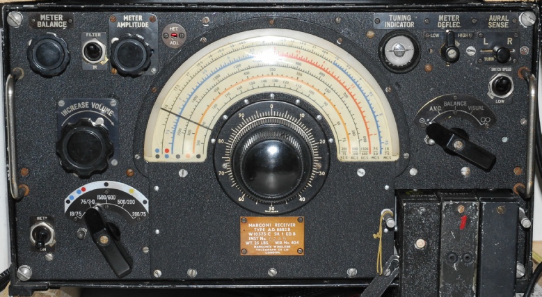
Receiver Type A.D. 8882B aka R.1155
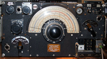
Marconi A.D. 8882B ... aka commercial R1155
The observant among you might notice that the photograph on the right is not actually of an R1155 but of a Marconi Receiver Type A.D 8882B, which for all intents and purposes is an R1155 in everything but name. It is likely that this is a prototype, hence why it carries the Marconi drawing number of AD8882B as opposed to the Air Ministry designation of R.1155. The inspection stamps throughout indicate that it is a genuine Marconi product.
I aquired this set in February 2010 for the sole purpose of restoring it. That is, the replacing of all the aging resistors and paper capacitors such that the working performance is the same as the the day it was manufactured.
Such receivers frequently appear on Ebay, but few are as unmodified as this one was. The only modification at the time of purchase was the removal of the ‘Cube’ capacitor in the centre of the chassis, and subsequently replaced with three modern electrolytics. Even the D.F. circuity was intact! Initial inspection suggested that someone had at some time at least planned to restore it since the top of the ‘piggy-back’ can and Coil-Box lid were highly polished. However, that appears to be all that was done. Much as the metal work was literally immaculate, the wiring was a completely different story! The 1940s rubber insulation on ALL the multi-strand wiring was completely perished to the extent that just touching it caused it to disintegrate. Maybe that was why the previous owner had ‘given up’? There was absolutely no way I was switching this thing on! Designed for instalation in aircraft, the type does not have an integral power supply, so one of my tasks was going to be the construction of a suitable PSU, and since the audio output is ‘headphones-only’, I might as well include a suitable audio amplifier for driving a loudspeaker too, and I might as well make it a valve job. Around this time, a good friend who I had previously restored an RA17 for, asked if I was up to the challenge of making a working 1155 from three ‘scrappers’. The bonus here was that out of the three scrap 1155s, there were fortunately two ‘cube’ capacitors which turned out to be in good condition, so I would be able to put one back in my AD8882B. Unfortunately like the majority of 1155s, all three ‘scrappers’ had no D.F circuity whatsoever. However, we are confident that all the bits can be obtained through time.
I had a very amusing conversation involving my Mother-In-Law a few days later. We were visiting my wife’s parents in mid February and since several items on which I was bidding were ending that night, I was logged into Ebay. To set the scene, my Wife’s parents are Geoff and Ann, and this is how the conversation went ...
Geoff: What are you bidding for?
Me: Bits for a 1940’s wartime radio, the sort traditionally fitted in Lancaster bombers, for instance.
Ann: Oh?
Geoff: What will you do with it?
Me: Get it working.
Ann: Oh?
Geoff: Then what?
Me: Use it ... Off course!
Ann: You won’t get much on it!
Geoff: Why not dear?
Ann: Radio was rubbish in those days (meaning that there were less radio stations!)
I said nothing, but just gave her a despairing look.
Back home, I tentatively began investigating the wiring in my ‘new’ receiver. There are actually three different types of wire used; Single-Strand with woven insulation, Multi-Strand with the dreaded rubber insulation and finally the coaxial cables. Interestingly, the rubber insulation in the coax cables was in excellent condition. I optimistically started pulling out the old perished wire and replacing it with modern PVC insulated wire but soon realised that drastic action was more appropriate. Realistically, like an old ‘property’, the set was going to require totally rewiring.
But first ...
Like I said right at the start of this website, I am no stranger to the R1155 type. My first one cost me 50 pence when I was a schoolboy. It had no tuning knob, but did appear to have a hole right through the chassis where V1 & V2 should be. At the time we liked to believe it was a bullet hole. But more likely it was actually made by a pick-axe! I later heard a tale recounted by an ex-RAF Corporal who told how after the war (WW2), when he was stationed at a bomber base somewhere in England, all the decomissioned radio equipment was lined up on the edge of a runway and he and others were instructed to go along the line and smash it. Perhaps my original 1155 was one of those. I got it working by comparing it to a complete specimin. To give an idea of how uninformed I was at the time. A friend and I had obtained what I now know to have been a complete ‘Gee Set’ and promptly stripped it with the optimistic idea of building an oscilloscope in the case, making use of the tube. The large tuning knob was ingeniously re-fitted to the front of my repaired 1155. The irony of this was, at the same time (1974), the Gee Set on display at the Imperial War Museum was missing the large knob. I did consider trying to sell them the one fitted to my 1155. I later obtained a second-hand and much modified Halicrafters SX-24 (octal valves replaced with B9A and B7G ones!) ... So I sold my 1155 for three times what it originally cost me! I think at some point I obtained a second 1155, and then the old chap over the road offered me a third one which had languished in his shed for many years. Sadly the shed hadn’t had a roof for many of these years so it was in a sorry state and was only used for scavenging parts. I cannot remember what happened to these radios. Some years later, I obtained the R1155 that had been the model against which I had repaired my original. I think this was actually an R1155B since it had all the extra radar filtering. Foolishly I swapped this for a precision DMM several years later. So now in 2010, I yet again I have an R1155, and this time I am keeping it!This one was actually advertised as a rare example of an R1155 prototype. This might actually be the case since I have come across an un-referenced article which stated that Marconi had already started work on the type A.D. 8882B before 1939 and that development was slow. Another reason for thinking that this is a prototype may be the fact that my set is fitted with the early (and unpopular with bomber crews) Type 13 tuning reduction drive, later changed to the Type 35. Add to that, the awful state of the wiring, it is easy to conclude that this is an early example of the type.
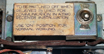
If the original Type 13 Tuning Mechanism hints that this is prototype, a discovery made under the chassis muddies the waters a bit. There is a switch located on the underside of the main tuning capacitor sub-chassis. Page 10 of the AD8882B manual states
‘Owing to the increased load on the L.T. Power unit, occasioned by the dual receiver arrangement, it is customary to remove valves V.1 (X.61M), V.2 (X.61M) and V.9 (BL.63) from the communications receiver. In certain later receivers an ordinary “On/Off” switch has been fitted on the underside of the chassis inside the receiver. In the “On” position the filament circuits are normal, all valve heaters being connected to the 6.3 volt supply. When such a receiver is fitted for communication use in a two receiver installation this switch should be placed in the “Off” position. It is then not necessary to remove any valves.’
‘Owing to the increased load on the L.T. Power unit, occasioned by the dual receiver arrangement, it is customary to remove valves V.1 (X.61M), V.2 (X.61M) and V.9 (BL.63) from the communications receiver. In certain later receivers an ordinary “On/Off” switch has been fitted on the underside of the chassis inside the receiver. In the “On” position the filament circuits are normal, all valve heaters being connected to the 6.3 volt supply. When such a receiver is fitted for communication use in a two receiver installation this switch should be placed in the “Off” position. It is then not necessary to remove any valves.’
In Peter Holtham’s excellent book ‘Restoring the Marconi R1155 Receiver’ includes a referenced excerpt from Sir Christopher Cockerell’s obituary which states that design started in October 1939 and took only 11 weeks from conception to installation. Peter was good enough to send me a pdf of an article published in Flight magazine from April 1947 showing two receivers described as AD8882Bs installed in a Short Solent Flying Boat. However, in one of the photographs of the installation, both AD8882Bs are clearly fitted with the later Type 35 Tuning Mechanism.
Unlike the Racal RA17 series, the R1155 is not exactly modular. Even removing the BFO/DF compartment is a major exercise. So this was going to be an all or nothing restoration ... Meaning that once I started stripping it down, there would be no stopping. With the R1155, there is little opportunity to do partial testing until well into the re-build phase. I have to admit that it was very disconcerting hacking away at the wiring ... But it was well worth it in the end.
Unlike the Racal RA17 series, the R1155 is not exactly modular. Even removing the BFO/DF compartment is a major exercise. So this was going to be an all or nothing restoration ... Meaning that once I started stripping it down, there would be no stopping. With the R1155, there is little opportunity to do partial testing until well into the re-build phase. I have to admit that it was very disconcerting hacking away at the wiring ... But it was well worth it in the end.
One thing in particular that makes the R1155 not the easiest of receivers to work on is the fact that the chassis and front panel cannot be seperated. I have seen some grotty looking chassis, however this one is in surprisingly good condition considering it’s age.
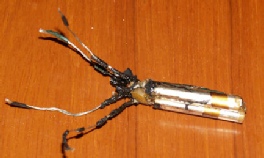
Old triple capacitor out of it’s can
The business of re-stuffing capacitors has been something that I have up until now resisted. However the R1155 has a total of thirteen chassis mounted tubular capacitors eight of which are mounted above the chassis. I was very relieved to find that all the large block capacitors were in sound condition as were all the silvered mica capacitors.
2 triple capacitors ready for re-stuffing
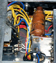
Hum Filter before
Since the eight tall tubular capacitors can be considered classic in terms of looks these were dutifully given the treatment as were the five other under-chassis bolt-ons. Regarding the tall tubulars, I used a 15mm pipe cutter to cut them open and used a combination of Araldite and super-glue to re-join the can afterwards. Finally I added a ring of self-adhesive tin-foil for good measure. Some people might want to take the re-stuffing business to the extreme by applying it to all tubular capacitors like those in the hum-filter. I was intrigued to see a wad of electricians cloth tape jammed between the sub-chassis and the lower end of the capacitor on the left. I opted to simply replace the two tubular capacitors with smaller new ones. My policy regards replacing resistors is to replace them ALL using new ones with a minimum dissipation of 800mW. Believe it or not, the small 27K resistor in the photograph on the right is actually a 1W job!
Hum Filter after
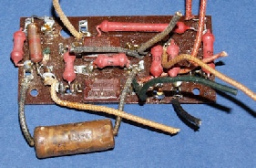
Bias-board before
Something that you notice about the R1155 is the occasional use of what might be termed non-standard value resistors. In the case of the Bias-Board, 3 x 10K resistors were
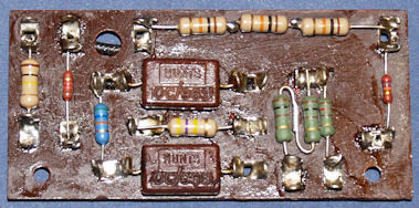
Bias-board after
required to make up to 30K and 2 x 100R resistors to make up to 200R. Don’t be tempted to use preferred values like 33K and 220R. This board is responsible for setting most of the bias voltages and for that reason, the resistance values are particularly important.
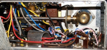
before
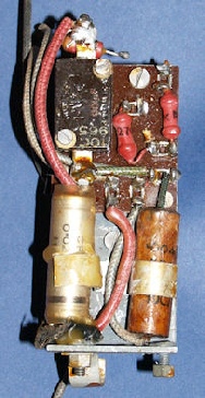
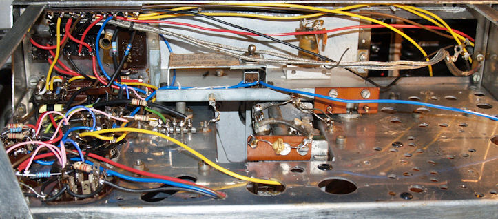
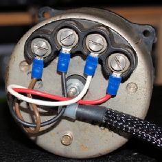
This is the area immediately behind the Jones connectors. The common conductor from the chassis mounted capacitor was severed and the wiring was somewhat shambolic to say the least.
after
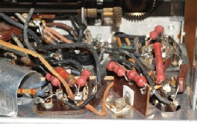
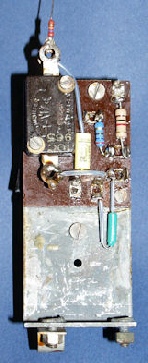
before
This is the area immediately behind the Range Selector. Not too untidy to start with but definitely looking better after refurbishment.
after
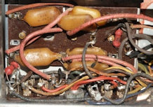
before
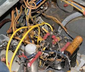
Finally, this is the area around the Master Switch. This area was host to some of the most shocking insulation degradation. The two bright yellow wires were part of my initial attempt to effect a repair without a total strip-down. It is interesting to note that not all R1155s exhibit this level of degradation. I can only put it down to a variation in rubber quality at a time when the majority of equipment wiring was cloth-rubber insulated.
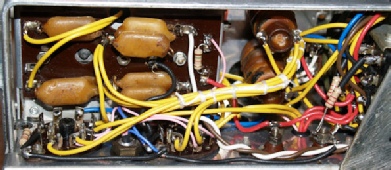
after
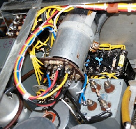
This is the D.F. / BFO Compartment. As can be seen, I have left the wiring in the D.F. Sub-compartment as it is since none of it is of the dreaded rubber insulated type. Also, the three metal-canned inductors are extremely fragile and difficult to remove. Note that I have replaced one of the silvered mica capacitors in the BFO. Although still within tolerance, the original was in a very sorry state. The BFO is self contained and can be tested outwith the main chassis.
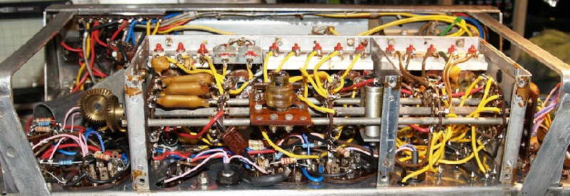
If there is one area within the R1155 that is going to frighten people away then it has to be the Coil Box. 15 trimmer capacitors, 18 inductors (although not all are variable) and 8 switch wafers!. However if you follow the steps in Peter Holtham’s book the process of refurbishment and re-fitting is actually remarkably painless. Although the wiring may look somewhat untidy, it is that way largely by necessity since the wiring needs to be kept as short as possible.
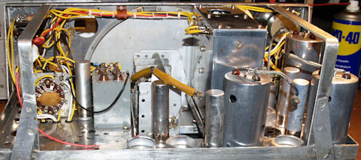
Here are a couple of photographs of the build at different stages. You can clearly see the self adhesive metal tape around the base of the tubular capacitors.
The area behind the Jones-Panel is now much tidier.
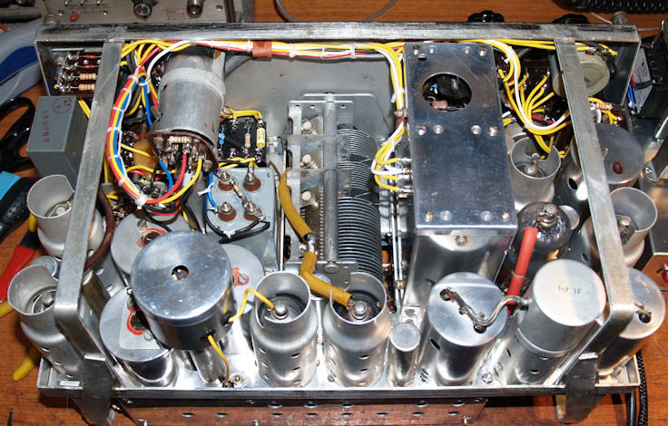
This is the finished article! Apart from a minor issue with a bad solder joint in the heater wiring, it worked first time. Alignment and calibration was very straight-forward as per Peter Holtham’s instructions. I haven’t had time to verify the D.F. Circuity. I was very fortunate to get hold of a perfect condition Direction Indicator Meter just a week after buying the receiver! But I will wait until I have built a suitable loop antenna before final testing. Since The D.F. Circuitry was left largely intact I am not expecting any problems.
Conclusions:
The R1155 is truly iconic ... just mention ‘Lancaster Bomber’ and some go weak at the knees! Different people have different motives for wanting an R1155. Some don’t even care if it works or not. My own reasons for obtaining one were two-fold. Firstly because I foolishly let at least two go, and secondly because I wanted to see how one would have performed when new. The R1155 represents a leap forward in aircraft communications for several reasons. It is relatively light (only 25 pounds), It covers a wide frequency range WITHOUT the need to physically change coils, and it provided for the first time, a reasonably accurate means of radio navigation. In fact there are more controls on the front of the receiver relating to the latter than to the receiver itself!
I admit that I was at an advantage when I started this project since my receiver was unmodified. Had it been otherwise, i.e. If it had been mutilated; had sections removed and/or modified etc. I have no doubt that I would still have completed the task, but the fact that the job was carried out from start to finish in only 25 days is testimony to Peter Holtham VK4COZ and his excellent book ‘Restoring The Marconi R1155 Receiver’. The dismantling process can be a bit disconcerting though, especially if you just paid serious money for your receiver! Peter guides you through the process of testing the various parts as they are removed before leading you into a carefully thought out re-assembly procedure. The bare chassis is remarkably light and I found it curiously satisfying to feel it getting heavier as the build progressed. I would stress that this is not a project for the inexperienced. The original R1155 was not particularly well made. In some cases the term ‘point-to-point wiring’ was applied literally. The area around the Master-Switch and immediately behind the Jones connectors is a good example of this. It won’t do your receiver any harm to take time to plan wiring routes so that you can eventually neatly bundle groups of wires together. Neat wiring will serve you well in the future should you need to do fault finding. Plenty of information on the R1155 is available on the Internet with original documents and diagrams freely available for download.
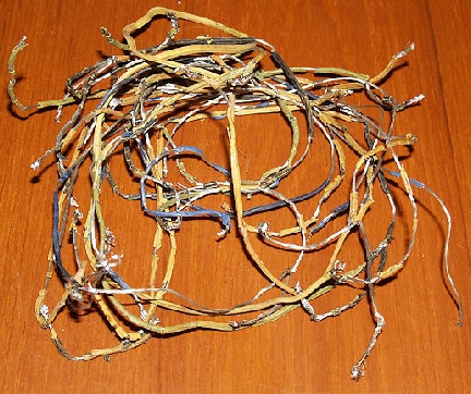
A small sample of the wiring removed from the A.D.8882B
As well as letting a couple of R1155s go over the last 35 years, I also have to confess to throwing out a box of Octal valves, many of which were no doubt ex-R1155! We live and learn. Spares for these receivers are not as unobtainable as you might imagine. Ebay can be an excellent source of parts, with sellers frequently advertising valves specifically for the R1155 ... But beware! Often those advertised are NOT actually suitable. The KTW63 (aka 6K7) for instance may be pin-for-pin compatible with the KTW61 or 62 but exhibits far less gain, so should be avoided. This is not to say that these sellers are deliberately trying to deceive you. It is possible that they themselves found such valves already installed and assumed that they were compatible. For example, I recently found a 6Q7 in the BFO compartment of an R1155, where an MHLD6 (or VR101) should be fitted. In this case the 6Q7 is almost acceptable however it is questionable if the same substitution could be made for V8.
So, how does the re-built A.D.8882B perform? Absolutely fantastic! There’s no other way to describe it. Far better than I remember any ‘original condition’ set performing. For AM reception, it is best to have the Master Switch at the AVC position (position 2). It is too often said that the 1155 is no good for SSB reception. For SSB and CW it is recommended to set the Master Switch to position 1 which disables the AVC. I then tuned the BFO for best audio from a 40m LSB signal. Resolved LSB on 40m and 80m is superb! During the day, I use the A.D.8882B for listen to the local AM broadcast station.
R1155 Valves and Equivalents ...
V1, V2 ......... VR.99A, CV1581, ECH35A
V4 ............... VR.99, CV1099, X66
V3, V5, V6 ... VR.100, CV1100, KTW61, KTW62
V7, V8 ......... VR.101, CV1101, MHLD6, DL63
V9 ............... VR.102, CV1102, BL63
V10 .............. VI.103, CV1103, Y61, Y63, 6G5, 6U5, EM34
The R1155 heater supply was actually DC and I have heard it said that an AC source should not be used since the set was not wired for AC. However this is not the case. An AC heater supply is perfectly suitable. The reason why the original heater supply was DC is simple; Power on the aircraft was provided by a ‘dynamotor’ which is ONLY capable of providing DC.
Another frequent error often made or suggested is to internally connect together the Fixed and Trailing Aerial inputs. This may simplify the RF input to some degree but is not advised since the two inputs are independently matched by separate transformers. Input switching in the R1155 is achieved by a combination of Master-Switch and Range Switch settings with the Fixed Aerial input being selected on ranges 1 and 2 and the Trailing Aerial for ranges 3 to 5.
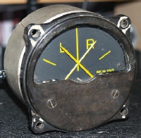
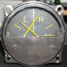
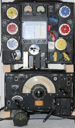
Now for the part of the R1155 that most people are unfortunately too eager to remove ... The D.F. Circuitry. Often this was removed to make way for an audio amplifier, usually in the form of a 6V6. I believe the R1155 was unique, being the only WW2 receiver specifically designed with integrated Direction Finding circuitry. This required an external Loop antenna and an ingenious Twin-Meter display unit which was quickly nick-named ‘The Drunken Men’ by aircrew. I remember being mystified by the settings on the Master Switch on my first R1155, not to mention the three controls referring to a meter, and just what on earth was Aural Sense and Switch Speed?
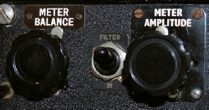
I will not go into the finer details of how the circuitry works since that can be found in great detail in the manual that is freely available from VMARS and other sources, but I can present a brief insight into what was involved. Firstly, the T1154 was required to be inhibited owing to the delicate nature of the ‘Visual Indicator Type 1’. This was accomplished by setting the ‘J-Switch’ to the ‘D.F.’ position. This also selected the shorter Fixed Antenna which ran from the ‘mast’ immediately behind the astrodome to one of the twin vertical stabilisers (in the case of the Lancaster). Once the receiver was tuned to the appropriate ‘beacon’, the operator (Wireless Operator) then set the Master Switch to ‘Balance’ and using the ‘Meter Balance’ control, set the needles to cross on the centre vertical line (see below). The Master Switch was then set to ‘Visual’ and the external Loop was rotated to re-centre the needles on the centre line.
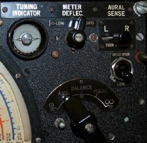
With this accomplished, making note of the angle on the Loop Antenna mechanism, and knowing the current flight vector, the pilot, with the aid of a second Visual Indicator atop the Glare-Shield was able to turn the aircraft onto the correct heading. The pilot simply had to keep the needles on the centre line. A task not necessarily as easy as it sounds, particularly if you are being hounded by night-fighters! The ‘Meter Amplitude’ and ‘Meter Deflec’ controls both influence the sensitivity of the Visual Indicator. The ‘Aural Sense’ switch was used for Aural ‘homing’ when the visual method was (for various reasons) not feasible. In this case, the Master Switch is set to the ‘figure eight’ setting. The two toggle switches are in a way related. The D.F. Circuitry employs a low frequency oscillator with two selectable speeds (80Hz and 30Hz). This results in a ‘hum’ which the ‘Filter’ switch can be used to reduce to some degree. Like I said above, this is a grossly simplified description. For a more in-depth description, refer to the appropriate manual, A.P. 2548A.
It is actually very simple to construct a workable loop antenna. I was absolutely amazed at how sensitive the system is to the loop direction with only a few degrees of azimuth sending ‘The Drunken Men’ from one extreme to the other. It is absolutely fascinating to watch the Visual Indicator working and a true testimony to Sir Christopher Cockerell’s team at Marconi. I have to remind myself that this is 1939 technology.
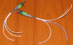
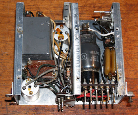
Two close-ups of the Visual Indicator Type 1. A very delicate instrument. I believe I was extremely lucky to get mine so soon after acquiring the receiver. Note the metal ‘sleeve’ into which the meter fits. I believe this to be mu-metal and thus serves to reduce magnetic influence on the sensitive movements.
Receiver Type A.D. 8882B, Instrument Number 6245
Unlike modern electronic equipment, where many components are date-stamped, it is virtually impossible to estimate the age of an R1155. The serial number will give some clues, but apart from that, there is little to shed light on the exact date of manufacture. This is the question that has been nagging me regards the age of my AD8882B ... I know that after WW2, for installation in commercial aircraft, the R1155 was modified and it reverted to its Marconi Type Number of A.D. 8882B. I recently came across a Marconi museum listing which confirmed that the ‘pre-development model’ for the R1155 was definitely designated the AD8882B. Note that the example on that website shows an AD8882B with the earlier Type-13 tuning mechanism but without the vernier scale. Note also that the ‘Instrument Number’ is 6004. Then see this page here which shows and describes a pair of AD8882Bs in a Shorts Solent Flying Boat, circa 1947. Note that both receivers in the photograph have the later Type-35 tuning mechanism. It would be illogical to revert to the older, less reliable, and harder to operate Type-13 mechanism simply because the installation was commercial. I have also found an article detailing the two types of tuning mechanism (Types-13 & 35) which provides a crucial and final piece to the puzzle. As well as confirming that the Type-35 mechanism was fitted from 1942, the article also revealed that the vernier scale behind the fine tune knob was only fitted to early R1155s. It was later omitted, (possibly as early as 1941) since it was inaccurate, due to the fact that the reduction was only approximately 100:1. This more or less confirms that my AD8882B is very likely from around early 1940, adding weight to the likelyhood that it is a prototype and as a result rather rare! Note that the ‘Instrument Number of my AD8882B is 6245. I do not believe that Marconi made over six thousand receivers before the Air Ministry issued the Type Number R1155. It is highly likely that ALL pre-development models bore a 4-figure Instrument Number beginning with 6.