Collins R-390/URR versus Racal RA17L
24 minute read
December 2018
I have a confession to make. If you had asked me a year ago if I had any interest in the Collins R-390 or its successor, the R-390A, I would very likely have said no. Not that I had anything against them ... I just figured that if I were to ‘dip into’ the Collins ‘universe’ there was a danger that I would get hooked. I just preferred to stay safe and restrict my collection to Racal equipment. However, as of October 2018 I confess that I am definitely a '390-convert'.
I have been refurbishing RA17s since 2009 (to date, 40 receivers) but until earlier this year (2018) my only experience with the Collins classic was limited to viewing various photographs. I will even admit that there were several aspects of the R-390 (or 390A) that I found unappealing. Firstly the front panel layout just didn't look right; the Veeder-Root counter was clearly a ground-breaking innovation in 1951, but its inclusion meant that this was no band-cruiser; and then there is that unbelievably complex gear-train! But when I was asked if I was up to the challenge of getting an R-390A up and running, I actually gave it some thought. The first thing that came to mind was that famous gear-train, but I said yes. My friend already owned one of my refurbished RA17Ls but had recently purchased a pair of Collins classics; a supposedly working R-390A and an R-390 which had seen better days and was missing several parts. Now, several months later, both receivers are up and running beautifully, and although this piece does include various 'work-in-progress' photographs of both receivers, this is more about comparing the Collins classic with the Racal classic.
When Racal was formed as a company in 1950, Collins was already an established manufacturer. When Racal won a contract to supply the Royal Navy with a variant of the Collins 51-J receiver, Collins refused to supply the licence (to manufacture their receiver), leaving the fledgling Racal with a contract to supply a receiver that it couldn't provide. I read somewhere that firstly Collins had stipulated that components used in the 51-J variant had to be sourced in the United States; something which Racal objected to since that would increase the cost. And secondly, Collins allegedly objected to their receiver being manufactured in what was clearly a bomb-damaged building with holes in the roof. I can see their concern! So without the Collins licence, Racal set about designing their own receiver. Enter the enigmatic genius Trevor Lloyd Wadley, a South African of British descent. In his biography (written by his sister, Mary Wadley von Hirschberg) the RA17 is described as being Wadley's receiver. However I had a chance encounter with a Racal engineer several years ago who confirmed that the design was very definitely Racal's, but it would never have come about had it not been for Wadley's ingenious drift-cancelling Local-Oscillator arrangement.
April 2021: I have recently seen proof that what became the RA17 was Wadley's design, not Racal's. I have seen photographs of Wadley's prototype (produced in his native South Africa) which pre-dates his involvement with Racal.
In fact, what is termed 'The Wadley Loop', actually dates back to the early 1940s when the young Wadley was an officer in the South African Signals Service (SSS) and stationed in Egypt. Dr. Brian Austin writes in Radio Bygones that during this time Wadley converted a conventional Hallicrafters receiver into a panoramic display with selectable 1MHz-wide segments without the need for mechanical band switching. This technique was ultimately referred to as the Wadley Triple Loop System. It was this system that Racal employed under licence from CSIR (Council for Scientific and Industrial Research) with Wadley's close guidance. As far as I can ascertain, at no point was Wadley actually employed by Racal. The RA17 would go down in history as the product which would launch Racal into the defence Electronics business and at its peak see it become the third largest Electronics Company in the UK. Who knows how different things would have turned out had Collins granted Racal a licence to produce their 51-J variant?
By the time the RA17 went into production, the R-390 had been replaced by the R-390A and the latter had been in production for several years. In terms of performance there is technically very little difference between the R-390A and the RA17 or any of its many variants. Some people might dispute this, siting current performance figures where both receivers are now over 60 years old. I am referring to ex-factory performance here. I will admit though that in 2018 an 'original' R-390 from 1952 is more likely to outperform an 'original' RA17 from 1957. This is entirely due to component quality, something that I will discuss later.
By the time the RA17 went into production, the R-390 had been replaced by the R-390A and the latter had been in production for several years. In terms of performance there is technically very little difference between the R-390A and the RA17 or any of its many variants. Some people might dispute this, siting current performance figures where both receivers are now over 60 years old. I am referring to ex-factory performance here. I will admit though that in 2018 an 'original' R-390 from 1952 is more likely to outperform an 'original' RA17 from 1957. This is entirely due to component quality, something that I will discuss later.
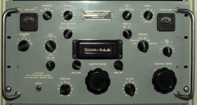
My R-390 prior to refurbishment
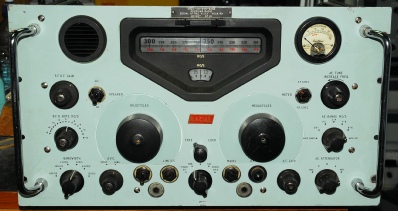
A recently refurbished RA17L
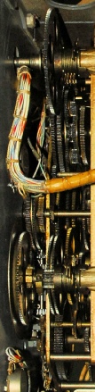
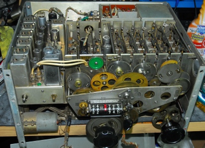
Mechanically the two are very different. The RA17 comprises four cast aluminium sub-assemblies whereas the R-390A is predominantly assembled from aluminium plate. Both receivers are modular, however the Collins is the easier of the two to 'split'. To give an example, in order to remove the 1st VFO module from the RA17 it is first necessary to remove the 2nd VFO. Removing the latter is further complicated since one of its retaining screws is hidden under a cover which can only be removed after taking out no less than 13 screws! It is the R-390A's modular design which gives rise to its slightly odd (in my mind) front panel layout. In terms of moving parts, the RA17 is by far the winner if we are looking for simplicity, with less than 10 gears involved in the entire tuning mechanism. I won't even try to count the number of gears in the R-390A, and the R-390 has even more!
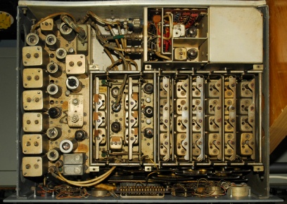
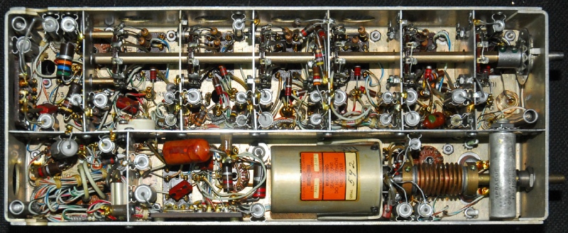
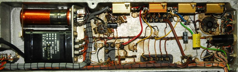
So the Collins definitely wins in terms of mechanical quality. But it is this level of quality that actually renders it harder to work on. Once you have removed the 2 VFOs from the chassis of the RA17 it is actually relatively easy to work on with very few components being difficult to reach. In contrast, the R-390 IF-Deck contains individual compartments that are just a little too small to easily access some components. (Below)
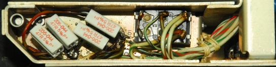
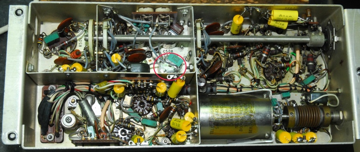 Underside of R-390A IF Deck (replacement filter circled).
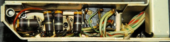
 R-390 IF Deck.
 R-390A IF Deck with the mechanical-filter cover removed whilst fitting a replacement filter..
 The 100KHz IF Strip from a MK2 RA17..
Unlike in the R-390A where the two anodes and two cathodes in each 26Z5W are simply strapped together; the R-390 employs 47-ohm current sharing resistors in series with each cathode.
I discovered that two of the resistors were actually snapped in two! Thus one half of each valve was out of circuit so that the remaing half was carrying twice the current. I replaced all four resistors with 5W wire-wound versions
Left: This is the underside of the Audio Deck. As with the rectifiers, the cathodes of the two 6082s also have 47-ohm current sharing resistors. Two of these were significantly cooked, so I replaced all four with 5W types. None of these repairs fixed the faults though. The throbbing turned out to be a faulty 6BH6. The ‘variable’ B+ line fault was much more subtle. Note the big 12W resistor bottom left. Needless to say it gets hot! Immediately adjacent are the valve bases for the two 5651 90V stabilisers. Essentially heat had taken its toll on these to the extent that the valve bases had gone high resistance and one of the valves (V609) was ‘unstriking’, causing the B+ line to drop. Both sockets were thoroughly cleaned and the associated wiring was replaced with PTFE covered wire. All resistors and capacitors associated with V607, V608 and V609 were replaced.
In terms of component quality, it is the original R-390 that gets my points. Even in 1952 Collins were employing discrete components far superior to those used by Racal in 1957 (and later!). The US military got a receiver with military-grade components whilst the Royal Navy got a receiver with commercial-grade components not dissimilar to those found in televisions of the time! This may have been a cost-saving exercise, given that the design of the RA17 incurred a £40K over-spend which nearly bankrupted Racal. Ironically the R-390A came about as a result of a request from the US military for a less expensive and easier to maintain receiver. Consequently the high quality Sprague Vitamin-Q capacitors were replaced with lower cost types. Although many will advocate replacing all the Vitamin-Qs found in R-390s, I have had no reason to replace any in mine (except those in the mains filter, which exploded!). However I did have to replace all the brown colour-banded capacitors in the R-390A.
Underside of R-390A IF Deck (replacement filter circled).
As part of my RA17 refurbishment process, I replace ALL the carbon resistors and ALL the tubular capacitors. Over the years I have developed a technique for quickly removing the component wires from the variety of tags and terminals. This involves heating the joint with a suitable soldering iron then gripping the wire with a pair of artery forceps. I then remove the heat and just as the joint cools I unwind it. This process actually results in quite a lot of the solder coming away with the wire. It sometimes takes more than one application of this technique before the wire comes away, after which the tag or terminal is finally cleaned of all remaining old solder by the application of solder-wick. This process isn't practical with the R-390/A however. The main reason being the nature of the tags and terminals. I will use the valve bases as an example. These are by far superior to those used by Racal throughout the production-life of the RA17 etc. However, in the Collins, the individual solder-tags on the valve bases are much finer (the metal is thinner) to the extent that it would be easy to actually rip the tags off when unwinding wires. When replacing components on the R-390/A I resorted to cutting the wires rather than de-soldering and possibly damaging the valve bases. I know that I am not alone in this practice.
Leaving the mechanical differences aside, I will now address the electronic architecture. The RA17 is often considered such a complex receiver that many owners treat it as something that should never be 'touched'. This is undoubtedly due to the knowledge that the 40MHz band-pass filter cannot be aligned without some form of sweep-oscillator and visual display. However, in my mind, the RA17 is actually electronically simple compared to the R-390. Before anyone points out the obvious fact that the R-390 contains 33 valves compared to 24 in the RA17L; The complexity isn't simply a matter of numbers … or is it? Both receivers provide selectable 1MHz wide tunable segments covering 0.5 to 30MHz (32MHz in the 390). Whereas the Collins employs a 32-way switch and 25 crystals to achieve this, the RA17 employs a continuously variable VFO (nominally 40.5 to 69.5MHz), a 'comb' of 1MHz harmonics, four mixer stages, a very sharp 37.5MHz band-pass filter and that much feared 40MHz filter (actually 40.5MHz). Look mum! NO SWITCHES!, and only one crystal in the entire receiver! (excluding the crystal lattice filters in the 3rd IF). The Racal method may sound complex, and even looking at the schematic, at first glance it may indeed appear so. This is the famed Wadley Loop . However once you break it up into its individual parts it isn't really that complex. A detailed description can be found here. To go from 1.5MHz to 29.5MHz on the RA17 takes no more than a couple of seconds. Try doing that on an R-390!
Both receivers employ triple-conversion, however the R-390 is only triple-conversion on the eight lowest bands with double-conversion being employed on the remaining 24 bands. Taking the RA17 first; the Intermediate Frequencies are 40.5MHz, 3.1 to 2.1MHz (tunable) and 100KHz. The R-390 does it this way: 17.5 to 25MHz (0.5 to 8MHz only), 3 to 2MHz and finally 455KHz. The double/triple conversion system found in the Collins is not uncommon. The Rhode & Schwartz EK-07 employs a similar architecture. Note that the first IF in the RA17 is pitched above the upper frequency limit of the receiver. Note also that it is not tuned, with selectivity being achieved by a clever interaction of the two band-pass filters (40MHz and 37.5MHz). This simplifies the circuit design. As in the Collins, the RA17 series does not employ any gain stages at the 1st and 2nd IFs.
Both the Collins and the Racal employ pre-selection before the RF amplifier stage. In the RA17 series, this is entirely manually selected and adjusted. In the R-390 and 390A the operation of the pre-selector is integrated into the tuning mechanism by way of that mesmerising gear-train to the extent that its operation is completely transparent to the user.
It is probably worth mentioning here that litterally all the tuning in the Collins is by permeability, i.e. Variable inductors as opposed to variable capacitors. I was pondering this fact and came to the conclusion that Collins went down this road for several reasons. Firstly, capacitors with flimsy tuning vanes can be problematic. Not only are they bulky, but they collect dirt over time, altering their value. There can also be issues with poor rotor contact. I have seen this arise in the 1st VFO in several RA17s where the symptom is usually variable VFO output level and sometimes total failure of the VFO. Secondly, permeability-tuned circuits are less likely to be affected by temperature and vibration. Finally, it was probably mechanically simpler to achieve.
Both the Collins and the RA17 series use the final IF to define the receiver selectivity. The R-390 employs no less than six amplifier stages (the R-390A has four), while the RA17 has only two. Both the R-390 and RA17 use L-C filters for the 'wider' bandwidths. The R-390A employs mechanical filters. The RA17 series employs lattice-type crystal filters for the 'narrower' bandwidths. This is a feature which is far superior to the series-resonant 455KHz crystal filter in the Collins.
R-390 IF Deck.
R-390A IF Deck with the mechanical-filter cover removed whilst fitting a replacement filter..
The 100KHz IF Strip from a MK2 RA17..
SSB as a mode was still very much in its infancy in the 1950s, hence the detector stages in the Collins and the Racal are nothing special; Simple diode detectors as opposed to product detectors. CW and RTTY were the modes of choice for military communications. Both types provide 600-ohm line outputs for feeding external equipment such as teleprinters. The front panel loudspeaker output in the RA17 is a bit of a joke (strictly just for local monitoring) and the R-390 and 390A don't even have a loudspeaker. Whereas the Racal can directly drive an external loudspeaker, the Collins requires an external matching transformer. The RA117 went some way to improving the audio output by using a 6AQ5 as the final audio stage as opposed to an EF91, which is afterall, an RF pentode.
If you want to see something that is gloriously over designed, then look no further than the power-supply in the R-390 with its seven valves. Compare this to the single GZ34 in the RA17 series. The power-supply in the Collins was dramatically simplified in the R-390A, with the valve count reduced to three. In order to make provision for an alternative DC to DC power unit, Collins ‘split’ the power-supply in both the R-390 and the R-390A such that the mains transformer and rectifiers are on their own sub-chassis whilst all smoothing and regulation circuitry is located on the Audio Deck.
If you want to see something that is gloriously over designed, then look no further than the power-supply in the R-390 with its seven valves. Compare this to the single GZ34 in the RA17 series. The power-supply in the Collins was dramatically simplified in the R-390A, with the valve count reduced to three. In order to make provision for an alternative DC to DC power unit, Collins ‘split’ the power-supply in both the R-390 and the R-390A such that the mains transformer and rectifiers are on their own sub-chassis whilst all smoothing and regulation circuitry is located on the Audio Deck.
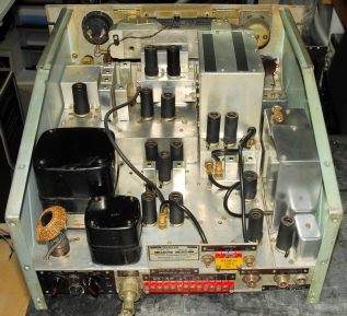
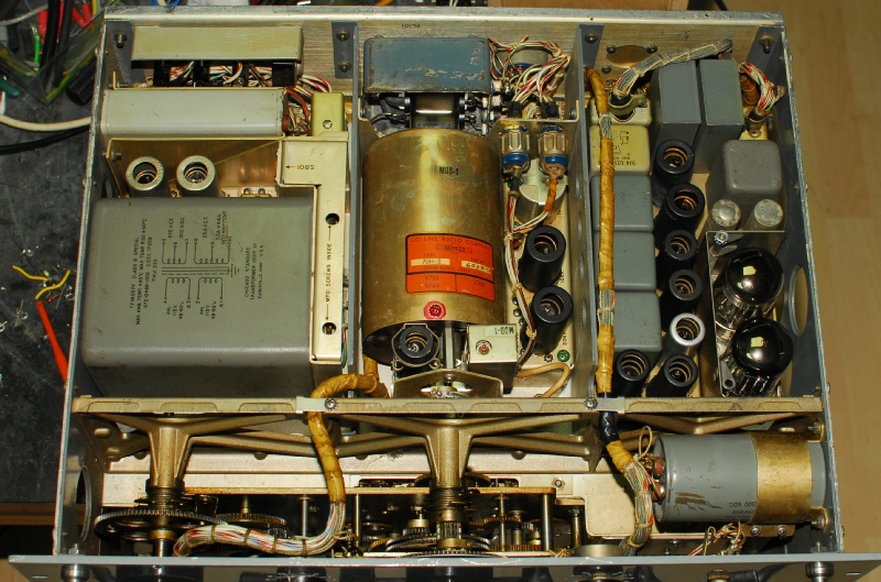
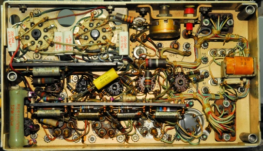
Above; The underside of my R-390 showing the transformer/rectifier assembly on the left with the main tuning PTO and calibrator in the centre and Audio Deck on the right where the valve in the silver can is a 6BH6. The two below that are 90V stabilisers. The two big valves are RCA or Tung-Sol 6082s. Both the R-390 and R-390A employ a pair of 26Z5W double rectifiers in the same way that Racal employed the trusty GZ34.
It is true to say that the more complicated a circuit, the more that can go wrong with it. Whereas the signal path in my R-390 worked well right from the start, the power-supply was a different matter. The symptoms included a loud throbbing after the receiver had been running for a while and a B+ line which would drop significantly before returning to 180V. In the end, I found two faults.
It is true to say that the more complicated a circuit, the more that can go wrong with it. Whereas the signal path in my R-390 worked well right from the start, the power-supply was a different matter. The symptoms included a loud throbbing after the receiver had been running for a while and a B+ line which would drop significantly before returning to 180V. In the end, I found two faults.
Unlike in the R-390A where the two anodes and two cathodes in each 26Z5W are simply strapped together; the R-390 employs 47-ohm current sharing resistors in series with each cathode.
I discovered that two of the resistors were actually snapped in two! Thus one half of each valve was out of circuit so that the remaing half was carrying twice the current. I replaced all four resistors with 5W wire-wound versions
Left: This is the underside of the Audio Deck. As with the rectifiers, the cathodes of the two 6082s also have 47-ohm current sharing resistors. Two of these were significantly cooked, so I replaced all four with 5W types. None of these repairs fixed the faults though. The throbbing turned out to be a faulty 6BH6. The ‘variable’ B+ line fault was much more subtle. Note the big 12W resistor bottom left. Needless to say it gets hot! Immediately adjacent are the valve bases for the two 5651 90V stabilisers. Essentially heat had taken its toll on these to the extent that the valve bases had gone high resistance and one of the valves (V609) was ‘unstriking’, causing the B+ line to drop. Both sockets were thoroughly cleaned and the associated wiring was replaced with PTFE covered wire. All resistors and capacitors associated with V607, V608 and V609 were replaced.
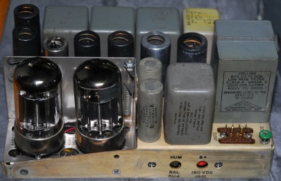
Left: The Audio Deck from my R-390 ... Note the two big Tung-Sol 6082s. The latter are somewhat rare, and when they do become available they are sought after by audiophiles. I had to replace one of mine since it occasionally flashed over. Fortunately I had a spare.
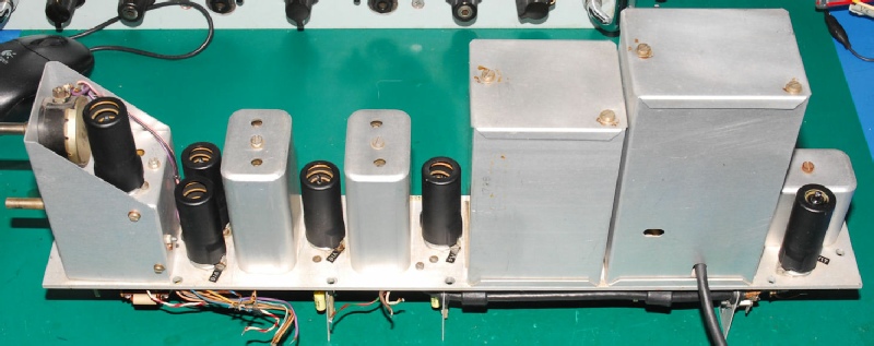
Below: In contrast to the R-390, the PSU/Audio compartment in the RA17 is simplicity itself!
Below: In contrast to the R-390, the PSU/Audio compartment in the RA17 is simplicity itself!
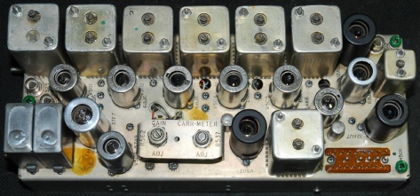
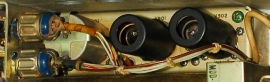
R-390 Calibrator
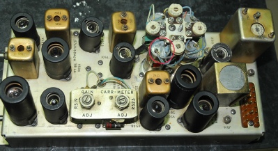
RA17 Calibrator
The signal path in my R-390 may have worked first time but there was a problem with the crystal calibrator. Someone had removed the 1MHz crystal! So I fitted one from a scrap RA17. Although both calibrators (R-390 and RA17) derive their 100KHz output from a 1MHz oscillator, the way this is achieved and then employed is completely different. In the Collins, the 1MHz oscillator is used to synchronise a 100KHz multivibrator. The signal is then injected into the signal path before the 1st RF amplifier. In the RA17 the 1MHz oscillator used in the Wadley Loop also provides the source of the 100KHz calibratior signal by way of a self maintaining regenerative circuit. The signal is injected into the signal path at the 2nd IF just prior to the 3rd Mixer.
Curiously, the calibrator in the Collins requires the use of the BFO (set to zero) to generate the beat-note. I find this odd since the BFO itself is only nominally calibrated. In the Racal the calibrator operates without the BFO, and since the calibrator is synchronised to the master 1MHz oscillator it is actually used to ‘check’ the BFO.
Curiously, the calibrator in the Collins requires the use of the BFO (set to zero) to generate the beat-note. I find this odd since the BFO itself is only nominally calibrated. In the Racal the calibrator operates without the BFO, and since the calibrator is synchronised to the master 1MHz oscillator it is actually used to ‘check’ the BFO.
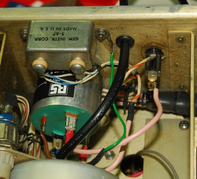
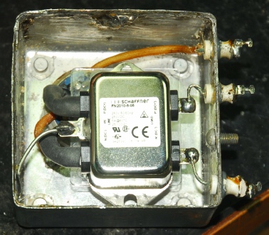
Both the R-390 and R-390A come with a filter on the mains input. (See here for my experience with the R-390 mains filter.) In both receivers, the mains filter is the actual point of input. In the R-390 the Amphenol filter assembly includes a 4-way plug which interfaces with a very solid screw-on socket on the end of the power-cord. Very likely as a cost-saving exercise, the mains cord for the R-390A is hard wired directly onto the mains filter input terminals which are located behind a removeable cover. Failure of the mains filter is a very common fault and the filter in my friend’s R-390A was indeed inclined to trip the mains RCD in his house. I replaced it with a nice big bolt-on cylindrical filter that I had acquired (see below)
The hole on the rear panel that the filter input terminals were originally accessible through was used to mount the new filter. I drilled a new hole through which I fed the mains cord.
I actually suspect that North American 390 users rarely encounter the faulty-filter issue since their line voltage is half of what we have here in the UK.
With that in mind I was having second thoughts about the capacitors that I had fitted in the Amphenol filter in my R-390. These were rated as 400V DC and as such were really only rated to 250V AC ... A bit close to our actual mains voltage which is declared as 230V but is generally 240V. So I removed the filter, desoldered the cover again and replaced the capacitors with ones rated at 1000V.
All was well until I was investigating the B+ line fault described earlier, when there was the classic high-voltage ‘crack’ and the radio went dead. I did the ‘sniff test’, and sure enough I detected a familiar acrid smell around the the rear of the mains filter. I should point out here that the rear of the filter has vent-holes ... It is not a sealed unit.
The mains fuse had blown but the B+ fuse was intact. Perhaps a bit hastily, I once again removed the filter: A task actually made easier by removing the main PTO first. I expected to find one of my new 1KV capacitors showing signs of failure. This however was not the case. I decided to fit an off-the-shelf self-contained filter, but what had caused the mains fuse to blow? Whilst fitting the new filter (see photograph on right) I found what had caused the mains fuse to blow. The wiring around the mains filter is not generous in terms of service loops. Adjacent to the mains filter is the 455KHz IF output socket. The cable to this connector runs very close to the neutral terminal on the filter; so close that there was actual contact. I had a close look at the coax cable... and sure enough there was a small black mark on the white insulation. A resistance check confirmed that the coax jacket had indeed been punctured. I carefully bent the terminal away from the coax and put some additional insulation around the coax outer jacket for extra protection.
Summing up ...
Trying to draw this objective comparison to a close before 2018 is behind us ...
As far as performance is concerned, my own view is that in terms of sensitivity (signal-plus-noise to noise ratio) there is actually little or no difference between the R-390 and the RA17L provided both receivers are free from degraded components and have both been correctly aligned. The KHz tuning on the R-390 is a tad coarse compared to the RA17. The RA17L’s lattice filters in the 300Hz and 100Hz IF bandwidths are superior to the derived 1KHz and 100Hz settings on the R-390 (and the R-390A). The Noise-Limiter in the Collins is superior to that in the Racal and the inclusion of selectable audio filters in the Collins is a useful plus. Also on the R-390’s side are the two panel meters and the fact that they are both meaningful. Whereas the North American versions of the RA17 and RA17L (RA17C and RA17C12) do have a genuine S-Meter as later supplied as standard in the RA117, us Brits had to be content with a meter which registered detector-diode current. The inclusion of a pre-settable squelch in the R-390 is a nice touch.
When it comes to ease of alignment, it is the Collins which wins. Yes there are fewer adjustment to be made in the Racal but the 40MHz Band-Pass filter simply cannot be aligned without specialist test equipment. The R-390 and R390A on the other hand do not require any such hardware. And it is interesting to note that it is actually possible to accurately measure the 390’s sensitivity using a signal generator and the two front-panel meters.
I am going to refrain from declaring an outright winner other than to say that I love my R-390 even if the tuning is not as fine as the RA17.
Then ...
and now!
As can be seen; When it arrived, my kindly gifted R-390 was missing a few parts and the MHz knob was definitely wrong!
Items missing:
Both stainless-steel handles, Veeder-Root cover, Dial Lock, Serial plate, Mains cord, DC input Fuse Holder, Bottom cover, Crystal Oscillator compartment cover and the cover over the main tuning racks.
Wrong or damaged parts:
MHz knob (possibly from another Collins RX), Carrier Meter and the four screws which along with the handles hold the front panel on. The extended shafts on the IF B/W and BFO controls were not original and the KHz knob and B+ Fuse Holder were damaged. The Zero-Adjust Clutch was seized.
The following items were obtained from various sources:
Replica Serial Plate, Mains cord complete with connector, Stainless-Steel handles.
I am indebted to Dave Schofield for supplying the following parts:
Carrier Level Meter, Veeder-Root Cover, 2 new Main Tuning knobs, the Dial Lock knob and the correct front panel screws (ALL screws in the R-390 and 390A are Phillips type).
I am also indebted to Lawrence Avery for 3D-Printing me three front-panel shaft bushes.
There is still no Dial-Lock mechanism, however I simply fitted a small potentiometer to hold the knob. The Zero-Adjust clutch was stripped down, degreased and reassembled. It now works!