Rapco 1804P9 GPS Disciplined Precision Frequency Source
7 minute read
August 2016
Last month I was exceptionally fortunate to be given a professional GPSDO … A Rapco 1804P9. Up until now I have been slaving my 9cm and 13cm transverters to my G3RUH-Clone GPSDO, which I have to admit is a very competent little box. However, over the years it has suffered a few failures. The ex-junk-box mains power module failed and no less than two Isotemp 134-10 OCXOs failed. So, latterly it has been running from one of the shack DC PSUs whilst the OCXO is now a Isotemp 143-141.
I will be honest; up until last week I had not heard of Rapco (now part of Spectracom) or their GPSDOs. A search on the Internet will turn up various Ebay auctions and several on-line discussions … all relating to the 1804M variant. However, detailed information is scant to say the least and the ONLY links purporting to ‘point’ to downloadable manuals turned out to be booby-trapped with malware … most curious! However I was able to identify a potential source of information and within a few hours I had a clutch of pdf manuals for various flavours of 1804 but not the P9 variant.
I will be honest; up until last week I had not heard of Rapco (now part of Spectracom) or their GPSDOs. A search on the Internet will turn up various Ebay auctions and several on-line discussions … all relating to the 1804M variant. However, detailed information is scant to say the least and the ONLY links purporting to ‘point’ to downloadable manuals turned out to be booby-trapped with malware … most curious! However I was able to identify a potential source of information and within a few hours I had a clutch of pdf manuals for various flavours of 1804 but not the P9 variant.
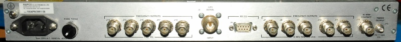
The Rapco 1804M provides a single 5MHz 50-ohm compatible sine-wave output which is GPS-Locked. The Rapco 1804P9 is a different beast altogether in that it provides no less than 5 distributed 10MHz 50-ohm compatible sine-wave outputs which are GPS-Locked. Apparently the 1804L17 is also a 10MHz source, but like the 1804M, it is single-output and the Trimble GPS RX is piggy-backed onto the Main PCB.

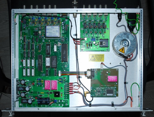
The photograph on the left shows the inside of the Rapco 1804P9. The large PCB on the left embodies the PSU (bottom), the RS-232 interface (4800 Baud 8N1), Hitachi CPU, 10MHz OCXO, 5 x 10MHz outputs,1pps Timing o/p and Alarm o/p.
The smaller multi-output board provides 5 x 1Hz TTL outputs (Square-Wave) slaved to the 1pps signal on the Main Board.
Finally the Trimble GPS RX is piggy-backed onto the square PCB bottom right. This appears to be a Lassen SKII.
Connection to the active antenna is via an N-Type socket on the rear panel.
Unlike my ‘RUH-Clone’ which makes use of the GPS-Locked 10KHz output from the Jupiter ‘GPS-engine’, the Rapco GPSDOs lock their OCXOs to the 1pps Timing Pulse from the Trimble GPS RX. This pulse is Time-Locked when the GPS acquires a geographic fix.
From documentation (1804L17) …
After power-on, the GPS receiver will normally provide a position fix in less than 5 minutes. If the unit has been moved a long way from its previous position, or if a long time has elapsed since it was switched on, then the 'Time to First Fix' could be as long as 15 minutes. When the GPS receiver has locked on to sufficient satellites the green GPS status indicator will come on, and the time output data (1 Hz and serial RS232 data)will be corrected to satellite time. …
Behaviour during warm-up ...
After a short period (2 to 3 min. typical, 15min. max) the GPS STATUS light will switch on, indicating that the GPS receiver has locked onto the satellites. At this point, the Time/Date information at all interfaces will be corrected from its initial (arbitrary) setting to the correct Time and Date derived from the satellite data, and the 1Hz Timing pulse output will be phase-stepped to align with UTC.
At this stage the frequency error of the reference oscillator may still be of the order of 5 in 10E7. Because of this frequency error, following the initial alignment sequence the 1Hz Timing marker will drift away from UTC at a rate of about 30 microseconds per minute. This drift rate will decrease as the oscillator continues to approach its correct frequency, and will continue to drop as the unit approaches its normal stand-alone accuracy.
A time delay of approximately 20 minutes from power-up is counted down by the software, after which the oscillator should have reached 'parts in 10E8' accuracy. At this point the 1Hz Timing output is again realigned with the GPS(UTC) pulse to correct the timing error that has accrued during the oscillator warm-up period. The 1Hz marker pulse will continue to drift away from UTC, but now at a reduced rate of about 3 microseconds per minute.
After a further period, of approximately 10 minutes, the CONTROL STATUS light will switch on; this indicates that the frequency control system has started drift correction. At this point, the Date/Time outputs (at the RS232 ports) will again be corrected to satellite time and the 1Hz marker pulse will be finally realigned with UTC. Thus the complete warm-up cycle from power-on to full performance is completed in less than 30 minutes, although in many applications the unit may be regarded as serviceable after half this time.
Once the CONTROL STATUS indicator is on, there will be no more phase-jumps in the 1Hz Timing signal, all further adjustment to maintain UTC alignment being achieved by 'steering' the oscillator frequency. The frequency drift-corrections involved in this process will take place at intervals of 512 seconds (8min 32sec).
The CONTROL STATUS indicator will remain on during normal operation unless the frequency reference should be disturbed by (say) a power break, GPS failure, severe temperature shock etc. Under such conditions, the oscillator control voltage is locked at the previous value (held in nonvolatile memory) until the drift-correction process has re-started.
Back in 2007 when I built my own GPSDO I used a ‘surplus’ PCB-based active antenna which I mounted in a little plastic box. This was mounted outside on a pole attached to the mast supporting my UHF and uWave antennas. A few years ago this failed and since low-cost GPS puck antennas had become available I bought one and simply placed it on the LNB arm of our redundant Freeview Satellite dish … and there it sat happily doing its job until last weekend.
Now with my newly acquired Rapco GPSDO I decided to attempt to mount the puck clear of the roof. In the process I removed the dish and the failed GPS PCB antenna from the mast.
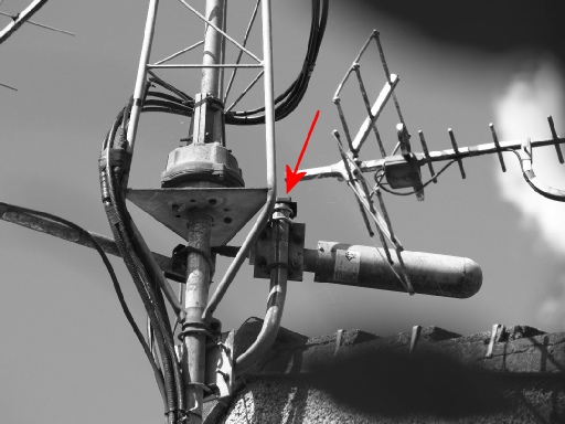
Using a U-bolt salvaged from the dish, I clamped an L-shaped piece of steel plate to the top of the pole that supports my 2.3GHz beacon yagi, and placed the magnetic puck on top; see the photograph on the left. It isn’t an ideal position since there will be some obstruction from the rotator body but the receiver never sees less than 8 satellites at any time. I should probably also provide some UV protective cover for the antenna.
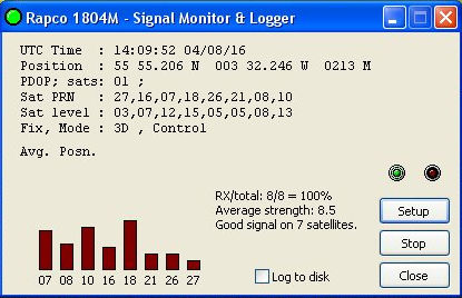
The RS-232 port on the rear of the 1804P9 provides an ASCI stream derived from the RAW NMEA data from the Trimble RX.
David GM8ARV has written a little program for displaying this on a Windows-based PC. Originally written for the 1804M there were one or two elements of data that were either missing or incorrect. However after providing David with a sample of the ASCII output from the 1804P9, he kindly made a few tweaks to his program so that the PDOP and Mode fields are now correct. The 1804P9 does not output an ‘Average Position’ periodically, so that field remains blank. On the other hand, the P9 outputs a parameter labelled ‘DAC output’ every 512s once a fix has been obtained and Control asserted. I believe this to be the Oscillator Steering Voltage in millivolts.
Using a U-bolt salvaged from the dish, I clamped an L-shaped piece of steel plate to the top of the pole that supports my 2.3GHz beacon yagi, and placed the magnetic puck on top; see the photograph on the left. It isn’t an ideal position since there will be some obstruction from the rotator body but the receiver never sees less than 8 satellites at any time. I should probably also provide some UV protective cover for the antenna.
The RS-232 port on the rear of the 1804P9 provides an ASCI stream derived from the RAW NMEA data from the Trimble RX.
David GM8ARV has written a little program for displaying this on a Windows-based PC. Originally written for the 1804M there were one or two elements of data that were either missing or incorrect. However after providing David with a sample of the ASCII output from the 1804P9, he kindly made a few tweaks to his program so that the PDOP and Mode fields are now correct. The 1804P9 does not output an ‘Average Position’ periodically, so that field remains blank. On the other hand, the P9 outputs a parameter labelled ‘DAC output’ every 512s once a fix has been obtained and Control asserted. I believe this to be the Oscillator Steering Voltage in millivolts.