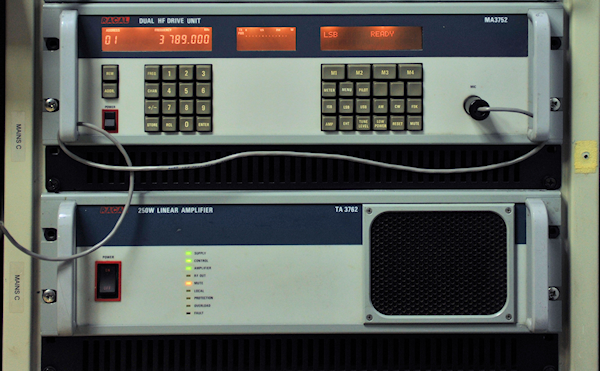
The MA3752 driving a TA3762 PA
15 minute read
This post is part of the series 'The Racal 3700 Series':
OK, it has only taken me close to two and a half years, but I eventually made the time to interface my MA3752 Dual HF Drive Unit with one of my two TA3762 250W Linear Amplifiers. This was part of the trove of 3700-series kit that I got from Danny Higgins, G3XVR, who sadly passed away a year ago (January 2020). I had split the trove with a friend who had a lot more room than myself, and he managed to beat me to it by almost a year. Having a lot more room, my friend has even managed to combine two TA3762s using an MA3772.
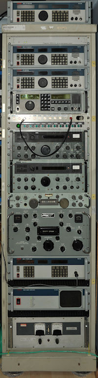
The photograph on the right is of my Right-Hand rack which is now complete, or more accurately, fully populated. Everything in the picture is fully functional, including the RA3702 (dual 3701) sitting on top. What looks like two more 3700-series receivers are indeed that; Sitting just below my Rapco GPS-Disciplined 10MHz Source are my RA3712 (dual 3711, 500KHz - 40MHz receivers) and RA3701, which sports the rather rare Sub-Octave Filter Unit.
The MA3752 and TA3762 are located under my R-390, each with a ventilation panel beneath them. Getting the MA3752 up and running required a little fault-finding. The Schaffner filter in the mains voltage selector exploded. No surprises there! This was duly sawn away and a plain-vanilla IEC chassis-plug was Araldited in its place. The Processor module then behaved oddly and BITE informed me that the system had suffered a total data-loss. Basically it was booting into an un-configured state. It was possible to manually enter all the essential settings etc. via the front panel, but none of it was subsequently stored. I'm not exactly sure what I did, but after treating some components on the Processor board to a squirt of Freezer Spray, I was eventually able to re-configure both Drive Units and store all the settings. This fault has NOT returned, fortunately.
One of the RF Output Modules was registering a low output during BITE. This was a particularly odd fault given that the Collector supply to the driver stages appeared to be pulsing. This turned out to be a failing surface-mount tantalum capacitor. Once replaced, the MA3752 was fully functional.
However, at switch-on the fault flag shows in the left-hand window. This is the result of a marginal drive level failure concerning the Dual 80MHz Reference Module. If left for about 15 minutes the fault clears, but to clear the flag, BITE must be run with respect to both Drive Units.
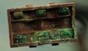
No sooner had I got the MA3752 up and running, than the right-hand display developed a fault. A vertical line of dots in the lower row had failed. Fortunately I was able to replace it with a display module from a scrapped front-panel assembly. Whilst the front panel was off I couldn't help notice the decidedly odd corrosion on two of the capacitor clamps. Danny had warned me that some of the metalwork was showing signs of corrosion. What I can't figure out is just how this came about since all the aluminium parts are Alochromed and the steel parts, like these clamps, are clearly treated in a similar manner. The two clamps were replaced with two taken from the scrap chassis.
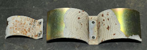
Left: The two badly corroded capacitor-clamps from the MA3752. Note the tree-ring-like nature of the corrosion on the larger twin-clamp. I can only surmise that this is due to a failure in the plating process.
We now turn our attention to the TA3762 Linear Amplifier. Ostensibly, this interfaces with the Drive Unit via a simple 4-wire Serial Link. However, there is also an Interlock facility which if not connected, prevents the amplifier from doing its thing. There is also an Interlock facility on each of the Drive Units. Initially I thought that one simply connected the Interlock connector on the Driver Unit to the Interlock connector on the Amplifier, but that's not how it works. It would appear that these connectors are actually there to interface with another piece of hardware such as the MA3772 1KW Combiner. At the end of the day, all one does is link two pins on the Amplifier connector and two pins on the Drive Unit connector. Simple, you might think, but an error has crept into the manual for the Drive Unit.
On page 2.3 of the Drive Unit Operator's Manual, under paragraph heading System Interlock Connection, it states '... SK2 pin 9 must be linked to 0V (pin 13)'. In actual fact 0V on SK2 is pin 15. The fact that there is a table on the same page relating to a similar connector on the Modulator Unit muddies the water a bit too. The instructions relating to the Interlock connector on the TA3762 are however correct. So, with the serial lead connected between the Processor module on the MA3751 and the rear of the TA3762, and the appropriate pins in the two Interlock connectors linked, I was ready to power up the PA. But what rating of fuse should be in the mains plug? Oddly this isn't specified in the manual, other than a line which states that the cable should be rated at 10A. This seemed a bit excessive to me so I started out with a 5A fuse ... such folly! It must be said at this point that the Power switch on the TA3762 is a serious affair ... definitely designed to carry more than a couple of Amps.
I switched it on and after a couple of seconds the top two LEDs on the front of the amplifier were lit. But then it appeared to power down. Actually the fuse in the mains plug blew. So I increased it to 10A ... but it still failed to power up. Aware of RACAL's propensity for fitting exploding mains filters in the 3700 series, I felt it was worthwhile investigating the filter on the back of the IEC connector. This wasn't the fault. The mains voltage was simply not getting through to the distribution strip tucked in behind the front panel, between the proprietary switching PSU and the Control Module. The loss of continuity turned out to be the Mains-Voltage selector switch. This was easily removed and on inspection it appeared to be not too difficult to take apart ... and since I didn't have a spare, repair, if possible, was the current option.
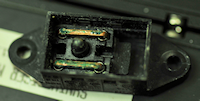
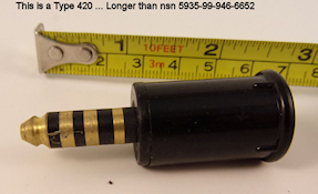
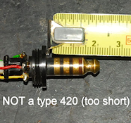
Note the difference between the two connectors in these photographs. The one on the right (nsn: 5933-99-946-6652) was advertised as a Type-420 but was clearly not. The mating part of the Post Office Type-420 on the left is longer than the connector on the right.
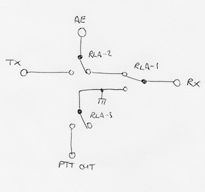
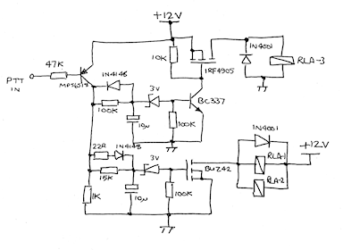
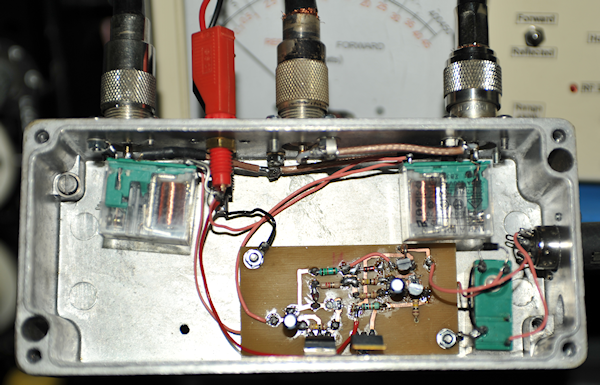
The last thing I wanted was for the receiver front-end to get a significant 'whiff' of the 250W from the amplifier. The obvious way to ensure such a thing is to sequence the switch-over process AND ensure that PTT to the MA3752 is only asserted after the coaxial change-over has taken place. With reference to the above schematics, the one on the left is primarily the coaxial (RF) path-ways, whilst the one on the right performs the sequencing. I take absolutely NO credit for this design as it is based on the well proven SEQ series of sequencer from DB6NT. When the Microphone PTT is pressed RLA-1 and RLA-2 change over simultaneously, the receiver input is grounded and the Aerial is connected to the output of the TA3762. About 150mS later, RLA-3 changes over and asserts the PTT input to the MA3752. When PTT is released at the microphone, the relays change back in the reverse order. Below is a photograph of the inside of the sequenced T/R Unit.
- The RA3700 Series
- The RA3701 HF Receiver
- The RA3712 Dual HF Receiver
- The MA3752 Dual HF Drive Unit
- The RA3702 Dual HF Receiver
- The TA3762 250W Linear Amplifier
- The MA3772 1KW HF Combiner
- The MA3752 driving a TA3762 PA
January 2021
RH-Rack complete
OK, it has only taken me close to two and a half years, but I eventually made the time to interface my MA3752 Dual HF Drive Unit with one of my two TA3762 250W Linear Amplifiers. This was part of the trove of 3700-series kit that I got from Danny Higgins, G3XVR, who sadly passed away a year ago (January 2020). I had split the trove with a friend who had a lot more room than myself, and he managed to beat me to it by almost a year. Having a lot more room, my friend has even managed to combine two TA3762s using an MA3772.
The photograph on the right is of my Right-Hand rack which is now complete, or more accurately, fully populated. Everything in the picture is fully functional, including the RA3702 (dual 3701) sitting on top. What looks like two more 3700-series receivers are indeed that; Sitting just below my Rapco GPS-Disciplined 10MHz Source are my RA3712 (dual 3711, 500KHz - 40MHz receivers) and RA3701, which sports the rather rare Sub-Octave Filter Unit.
The MA3752 and TA3762 are located under my R-390, each with a ventilation panel beneath them. Getting the MA3752 up and running required a little fault-finding. The Schaffner filter in the mains voltage selector exploded. No surprises there! This was duly sawn away and a plain-vanilla IEC chassis-plug was Araldited in its place. The Processor module then behaved oddly and BITE informed me that the system had suffered a total data-loss. Basically it was booting into an un-configured state. It was possible to manually enter all the essential settings etc. via the front panel, but none of it was subsequently stored. I'm not exactly sure what I did, but after treating some components on the Processor board to a squirt of Freezer Spray, I was eventually able to re-configure both Drive Units and store all the settings. This fault has NOT returned, fortunately.
One of the RF Output Modules was registering a low output during BITE. This was a particularly odd fault given that the Collector supply to the driver stages appeared to be pulsing. This turned out to be a failing surface-mount tantalum capacitor. Once replaced, the MA3752 was fully functional.
However, at switch-on the fault flag shows in the left-hand window. This is the result of a marginal drive level failure concerning the Dual 80MHz Reference Module. If left for about 15 minutes the fault clears, but to clear the flag, BITE must be run with respect to both Drive Units.
No sooner had I got the MA3752 up and running, than the right-hand display developed a fault. A vertical line of dots in the lower row had failed. Fortunately I was able to replace it with a display module from a scrapped front-panel assembly. Whilst the front panel was off I couldn't help notice the decidedly odd corrosion on two of the capacitor clamps. Danny had warned me that some of the metalwork was showing signs of corrosion. What I can't figure out is just how this came about since all the aluminium parts are Alochromed and the steel parts, like these clamps, are clearly treated in a similar manner. The two clamps were replaced with two taken from the scrap chassis.
Left: The two badly corroded capacitor-clamps from the MA3752. Note the tree-ring-like nature of the corrosion on the larger twin-clamp. I can only surmise that this is due to a failure in the plating process.
We now turn our attention to the TA3762 Linear Amplifier. Ostensibly, this interfaces with the Drive Unit via a simple 4-wire Serial Link. However, there is also an Interlock facility which if not connected, prevents the amplifier from doing its thing. There is also an Interlock facility on each of the Drive Units. Initially I thought that one simply connected the Interlock connector on the Driver Unit to the Interlock connector on the Amplifier, but that's not how it works. It would appear that these connectors are actually there to interface with another piece of hardware such as the MA3772 1KW Combiner. At the end of the day, all one does is link two pins on the Amplifier connector and two pins on the Drive Unit connector. Simple, you might think, but an error has crept into the manual for the Drive Unit.
On page 2.3 of the Drive Unit Operator's Manual, under paragraph heading System Interlock Connection, it states '... SK2 pin 9 must be linked to 0V (pin 13)'. In actual fact 0V on SK2 is pin 15. The fact that there is a table on the same page relating to a similar connector on the Modulator Unit muddies the water a bit too. The instructions relating to the Interlock connector on the TA3762 are however correct. So, with the serial lead connected between the Processor module on the MA3751 and the rear of the TA3762, and the appropriate pins in the two Interlock connectors linked, I was ready to power up the PA. But what rating of fuse should be in the mains plug? Oddly this isn't specified in the manual, other than a line which states that the cable should be rated at 10A. This seemed a bit excessive to me so I started out with a 5A fuse ... such folly! It must be said at this point that the Power switch on the TA3762 is a serious affair ... definitely designed to carry more than a couple of Amps.
I switched it on and after a couple of seconds the top two LEDs on the front of the amplifier were lit. But then it appeared to power down. Actually the fuse in the mains plug blew. So I increased it to 10A ... but it still failed to power up. Aware of RACAL's propensity for fitting exploding mains filters in the 3700 series, I felt it was worthwhile investigating the filter on the back of the IEC connector. This wasn't the fault. The mains voltage was simply not getting through to the distribution strip tucked in behind the front panel, between the proprietary switching PSU and the Control Module. The loss of continuity turned out to be the Mains-Voltage selector switch. This was easily removed and on inspection it appeared to be not too difficult to take apart ... and since I didn't have a spare, repair, if possible, was the current option.
I fully expected the contacts to be tarnished, or maybe showing signs of burning. What I did not expect was the massive amount of damp-induced corrosion as seen in these two photographs. A few squirts of De-Oxit, a wire-brush and a wash-down with IPA and the switch was as good as new.
So now the TA3762 powered up and stayed on ... progress! Now to get the MA3752 'talking' to it. This wasn't as easy as I had anticipated. The MA3752 User Manual does provide what appears to be all the settings, however there was some confusion regarding some of the rs-232 parameters. The TA3762 User Manual on the other hand provides largely the same instructions but fortunately the rs-232 parameters are more concise. For the purpose of 'marrying' the TA3762 to the MA3752 it is necessary to 'set' one of the DIP-switches on the top of the amplifier. Only then can you assign it a local address/number. Once that is done, the DIP-switch can be reset.
Control of the TA3762 is by way of the front panel of the MA3752. Even the BITE on the amplifier is initiated from the Drive Unit, and it is very reassuring to see all the LEDs switching off and on and then have the display on the MA3752 indicate that the test completed with no faults.
Once the serial-link is made, the options available via the Drive Unit front-panel include all the amplifier options, like 1, 2 or 4 TA3762s. The centre display on the MA3752 also now displays the VSWR that the PA is 'seeing' and the Output Power. I'm assuming that if it was a 2 or 4 PA configuration then the centre display would change accordingly.
Now for the 'Human Interface'. The MA3752 has a front-panel 4-pole jack-socket for a microphone or headphones. The correct matching plug is a Type 420, originally made for British Telecom. It is sometimes known as a PO (Post Office) type 420.
Note the difference between the two connectors in these photographs. The one on the right (nsn: 5933-99-946-6652) was advertised as a Type-420 but was clearly not. The mating part of the Post Office Type-420 on the left is longer than the connector on the right.
Getting power out of the TA3762 was not exactly straight-forward (more on that later) ... but suffice to say, it effortlessly generated just short of 300W between 1.8MHz and 30MHz into my 500W dummy load.
My plan was to use the MA3752 and TA3762 in conjunction with my RA3701 (or RA3702 or RA3712). Initially this sounded straight-forward, but the more I looked into it, the more I came to realise that these units were never intended to be used in a transceive configuration! In fact, a common configuration would see the transmitter and receiver sited at different locations. To that effect, the TA3762 is designed to be permanently connected to its own antenna. The same is so for the receiver.
Also, there is no way for an MA3752 to be slaved to a matching RA3712 directly. The only way to do this is via a custom controller with connection to SK1 on the each Processor Module, as some people have indeed done. And since the MA3752 does not have a 'Tuning Knob', the TX frequency has to be manually entered via the key-pad, or an external controller. Quality kit, but definitely NOT designed for band-cruising!
Then there is the requirement to switch the antenna from the receiver to the transmitter at the appropriate time. I would need an external coaxial switching system which would also provide suitable receiver protection. Here is what I came up with ...
RF and PTT Switching
Sequencer Schematic
The last thing I wanted was for the receiver front-end to get a significant 'whiff' of the 250W from the amplifier. The obvious way to ensure such a thing is to sequence the switch-over process AND ensure that PTT to the MA3752 is only asserted after the coaxial change-over has taken place. With reference to the above schematics, the one on the left is primarily the coaxial (RF) path-ways, whilst the one on the right performs the sequencing. I take absolutely NO credit for this design as it is based on the well proven SEQ series of sequencer from DB6NT. When the Microphone PTT is pressed RLA-1 and RLA-2 change over simultaneously, the receiver input is grounded and the Aerial is connected to the output of the TA3762. About 150mS later, RLA-3 changes over and asserts the PTT input to the MA3752. When PTT is released at the microphone, the relays change back in the reverse order. Below is a photograph of the inside of the sequenced T/R Unit.
When the Antenna port is connected to the TA3762, and the Receiver port is grounded, the isolation between the TA3762 port and the Receiver port is in excess of 65dB. Thus, if the amplifier is delivering 300W, the power at the receiver front-end will be in the region of 100uW. I'm happy with that.
So now we have a viable system, but not quite ready to go live. As I said previously, getting power out of the TA3762 is not exactly straight-forward. I believe the reason for this is because the hardware is designed to run unattended, i.e the transmitter would be set to a chosen mode and frequency, transmit would be enabled and then the kit would be largely left alone. Also, the front panel microphone connector is not the prime source of modulation. In the case of a remote station, the modulation drive very likely arrived via a standard telephone link and was routed to the D-type connector on the Modulator module in the MA3752 Drive Unit. In fact the only point where a CW signal can be initiated is via this rear-panel connector.
Operating the MA3752 (and the TA3762) via the front panel has proved a tad tricky. There appears to be a strict start-up procedure, particularly if the system has been switched off and/or if the transmit frequency has changed. I have found instances where the PTT input appears to be by-passed, putting the system onto transmit. In this case the only only way 'out' is to hit the 'AMP' button on the MA3752 which is used to toggle the PA On or Off.
I have found that the following start up procedure works ... most of the time:
1. Assume that the MA3752 has been switched on for at least 15 minutes and that there are no unexpected faults being flagged.
2. Ensure that MIC input and PTT control are selected, along with the Mode and chosen Frequency.
3. Switch on the TA3762.
4. From the MA3752, initiate the Amp Test (BITE) and wait for it to conclude.
5. Press AMP to set the amplifier to ON (standby) condition.
6. Initiate a full system test (MA3752 BITE). This will take about 10 minutes. (see below for explanation)
7. Now press and hold the microphone PTT and then press RESET (on the MA3752). This will cause the TA3762 to choose the correct Low-Pass filter and verify that the load conditions are within acceptable limits. If all is OK the word READY will appear in the RH display of the MA3752 and PTT will work. That's the theory ...
Now to explain this seemingly odd procedure:
Step 4 is necessary since while the TA3762 is not powered, the MA3752 will report that it has lost its link with the TA3762. Running the AMP TEST re-asserts the link and clears the 'fault'.
Step 6 ... On some occasions the MA3752 overrides the external PTT. This step is the only way I can ensure that manual PTT works! I have no idea why!
Step 7 is necessary to prime the TA3762 for transmit.
If the TA3762 has a 'Dark Side' it is this: If the input frequency is changed significantly, the system automatically initiates a RESET. When it does this it 're-tunes' the Low-Pass Filter and checks the load conditions. In order to do this it appears to output full power for a few milliseconds! This is not going to be a problem in a system where the transmitter output is permanently connected to the antenna. But in my situation, where the receiver and transmitter share the same antenna, this is a problem. Until external PTT is asserted, the amplifier output is open-circuit. So when the RESET function generates the short burst of RF, it is into an open-circuit, the BITE detects a high VSWR and forces the system into Reduced-Power Mode which needs to be manually cleared. The only way around this is to force any antenna change-over system into TX mode while the RESET is initiated.
So while it works, and I have used it on the air on 40m, this has to remain classed as a 'Proof Of Concept' project for the moment ... mainly because high levels of RF have a tendency to knock our Broadband router 'off' ... and with my wife currently working from home, loss of internet connection is NOT acceptable.