A forced re-vamp of the 4m Transverter
5 minute read
May 2009
About 6 weeks ago my IC706MK2G did something very odd which required it to be sent back to IcomUK for repair. When they examined it they were most concerned since it appeared to them that it had suffered a major voltage spike. However, no other piece of equipment running off the same PSU was affected. As it turned out, the damage wasn’t as severe as first thought. Only three devices needed replacing. When I got it back I powered it up on the bench and all appeared OK. However once installed on the shelf with everything connected, the T/R relay on the PA board buzzed, causing it to switch rapidly from transmit to receive continuously. I knew from experience that this was very likely an un-seated ribbon cable between the PLL board and the PA board. I opened the radio up, re-seated the cable and all was fine. Then about two weeks ago disaster struck. This was the weekend of the UHF contest. The conditions were worse than flat. I had heard absolutely nothing on the Saturday and switched everything off in disgust. On the Sunday, I switched everything back on. It appeared that conditions were still lousy so I left the shack. A few hours later, I returned to find the 706 off and the fan on my Newmar 35A PSU going full-belt! This Recent acquisition is used to power the 737 and the 706, however at the time, only the 706 was on. But not only was the 706 off, but the 4m transverter was stuck on transmit.
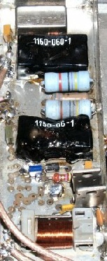
To be honest, the 4m transverter has had a chequered history, with problems with the relays on the 2m to 10m board. What greeted me when I opened it up took me by complete surprise. The relays either side of the input attenuator were melted! (see the photograph on the left) And a couple of resistors associated with the two power transistors bottom right were completely burned out. On the 706, investigations revealed a dead short which appeared to be the VHF/UHF PA MOSFET; an obsolete device these days! As I said, disaster. And this was a bank holiday weekend! It was Tuesday before I could speak to IcomUK, who thankfully informed me that they had three PA devices in stock. I boxed up the 706 and sent it back. So imagine may relief when I telephoned them a week later for a progress report and they informed me that it was invoiced and awaiting dispatch and that I should get it the next day. This was being treated as a workshop warranty repair. Back-tracking slightly here ... Early 706’s like the MK1 were notorious for blowing up transverters since they deliver a full power spike at 144MHz for about 200ms even though the power level is set to minimum, due to the way the power level is controlled. The MK2 is the same. However, the MK2G, although employing the same power control principle, only delivers a 2ms spike which is acceptable. BUT, if as happened to me, something causes the T/R relay to buzz, and assuming that the entire transceiver is rapidly switching from receive to transmit and back again ... and the microphone is connected, it can be seen that in SSB mode, the microphone will pick up the noise of the buzzing relay and deliver a string of 2ms 20W pulses into whatever the 706 is connected to: In my case, the 4m transverter. And because of the rapid train of pulses (possibly 20Hz?) then the rms value is likely to be significant, causing the input attenuator to overheat ... Which is how I believe one of the relays came to be so incredibly melted (You have to admit it is impressive). Obviously something gave out in the PA. Fortunately for all concerned, it wasn’t the PA device but a capacitor (C242) in the output circuit which had failed. At my request, Icom also replaced the two ribbon cables that service the PA board, as a precaution against the likelihood of this state re-occurring.
My initial thoughts were to scrap the 4m transverter and build a completely new one, but as I poked around inside it appeared that the only casualties were the two relays and the two resistors (and possibly the two transistors). Then it struck me that given the checkered history of decidedly odd relay problems, it was time to re-think the 144MHz-28MHz transverter side of things. (This is a dual-conversion transverter with a 28MHz Intermediate frequency). No gain is required in the receive converter (28MHz to 144MHz) but some gain is required in the transmit path to drive the 28MHz to 70MHz up-converter. To this end, I simply sawed the first two active stages off the old 28MHz PA!
My initial thoughts were to scrap the 4m transverter and build a completely new one, but as I poked around inside it appeared that the only casualties were the two relays and the two resistors (and possibly the two transistors). Then it struck me that given the checkered history of decidedly odd relay problems, it was time to re-think the 144MHz-28MHz transverter side of things. (This is a dual-conversion transverter with a 28MHz Intermediate frequency). No gain is required in the receive converter (28MHz to 144MHz) but some gain is required in the transmit path to drive the 28MHz to 70MHz up-converter. To this end, I simply sawed the first two active stages off the old 28MHz PA!
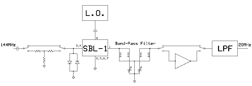
The basis of the revised 144MHz to 28MHz transverter
The rear-panel variable capacitor was replaced with a couple of trimmer capacitors (nominally 27pF when set). The output of the small amplifier was measured at about 0.5mW on transmit so the input attenuator in the next stage was adjusted accordingly.
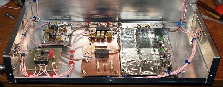
The re-vamped 4m transverter is now simpler, uses more reliable relays and since the drive into the second converter stage is now only 0.5mW as opposed to 1W, overall current drain is much less. The output is still a good 30W at 70MHz.