A Modular Transverter for 3cm
5 minute read
July 2014
This is a project that has been in the pipeline for a long time. Also it isn’t actually mine. For some time, my good friend Alan, GM0USI had been ‘collecting’ the necessary modules designed by Chris Bartam, GW4DGU. Alan is no stranger to 3cm and already has a fairly ‘potent’ portable system for that band. I, having regressed into the realm of thermionic valves lately, suspect that this ‘second’ transverter is Alan’s attempt to entice me to go out portable on 3cm occasionally.
For those unfamiliar with Chris’s modular transverter design, a breakdown of the system can be found here. I will admit that when Alan approached me and asked if I would would be up for building this transverter, I was quite excited. Actually I think what Alan actually said was “I have another wee job for you”. The modular design actually lends itself to innovative construction and I initially thought about a cube construction with each of the modules occupying a ‘face’. Whereas that is undoubtedly possible, it isn’t really practical. So for a few weeks Alan and myself mulled over various layouts and ergonomics. The main prerequisites were that it should be small (and light) and be interchangeable with Alan’s other portable microwave transverters. i.e. it had to fit onto Alan’s portable tripod and be waterproof.
This is what we came up with …
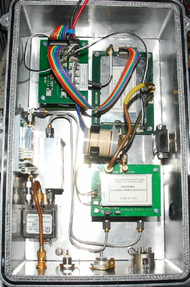
The photograph on the left is actually quite far on in the build but it does give an idea of the concept. Chris’s use of standardised module dimensions made stacking a logical option. Four of the modules are identical in size but it wouldn’t be practical to stack all four. Top-left in the photograph we have the distribution board mounted on top of the 2m IF interface board. Top-right is the Up-Down Converter module. Bottom-right is the 40MHz Reference Oscillator mounted on top of the 10GHz T/R board. Between the Up-Down Converter and the T/R board is the 10GHz Bandpass Filter.
The 2W 10GHz PA is mounted on the side-wall of the enclosure. At time of writing, Chris has not made available a matching 10GHz RX Pre-Amp so Alan provided one by DB6NT. The coaxial relay is a 12V fail-safe type driven from the distribution board.
Ideally we would have liked for ALL the connectors and switches to be mounted on the bottom face but space was limited. Left to right the connectors at the bottom are … 10GHz (SMA), 10MHz from GPS-Locked source (TNC), 144MHz IF (N-Type), 12V DC (XLR)
For those unfamiliar with Chris’s modular transverter design, a breakdown of the system can be found here. I will admit that when Alan approached me and asked if I would would be up for building this transverter, I was quite excited. Actually I think what Alan actually said was “I have another wee job for you”. The modular design actually lends itself to innovative construction and I initially thought about a cube construction with each of the modules occupying a ‘face’. Whereas that is undoubtedly possible, it isn’t really practical. So for a few weeks Alan and myself mulled over various layouts and ergonomics. The main prerequisites were that it should be small (and light) and be interchangeable with Alan’s other portable microwave transverters. i.e. it had to fit onto Alan’s portable tripod and be waterproof.
This is what we came up with …
The photograph on the left is actually quite far on in the build but it does give an idea of the concept. Chris’s use of standardised module dimensions made stacking a logical option. Four of the modules are identical in size but it wouldn’t be practical to stack all four. Top-left in the photograph we have the distribution board mounted on top of the 2m IF interface board. Top-right is the Up-Down Converter module. Bottom-right is the 40MHz Reference Oscillator mounted on top of the 10GHz T/R board. Between the Up-Down Converter and the T/R board is the 10GHz Bandpass Filter.
The 2W 10GHz PA is mounted on the side-wall of the enclosure. At time of writing, Chris has not made available a matching 10GHz RX Pre-Amp so Alan provided one by DB6NT. The coaxial relay is a 12V fail-safe type driven from the distribution board.
Ideally we would have liked for ALL the connectors and switches to be mounted on the bottom face but space was limited. Left to right the connectors at the bottom are … 10GHz (SMA), 10MHz from GPS-Locked source (TNC), 144MHz IF (N-Type), 12V DC (XLR)
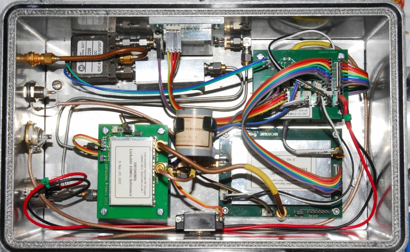
The photograph above is a little bit further on in the build. The toggle-switch on the side wall opposite the PA is a weather-proof design. The purpose of this switch is to enable selection of either the built-in 40MHz reference or an external GPS-Locked 10MHz source. Note that the modules are actually mounted on an internal sub-chassis. This method was chosen so as to keep to a minimum the number of holes in what is essentially a weather-proof box. The sub-chassis is screwed (blind-tapped) down onto four tapped ledges on the floor of the box.
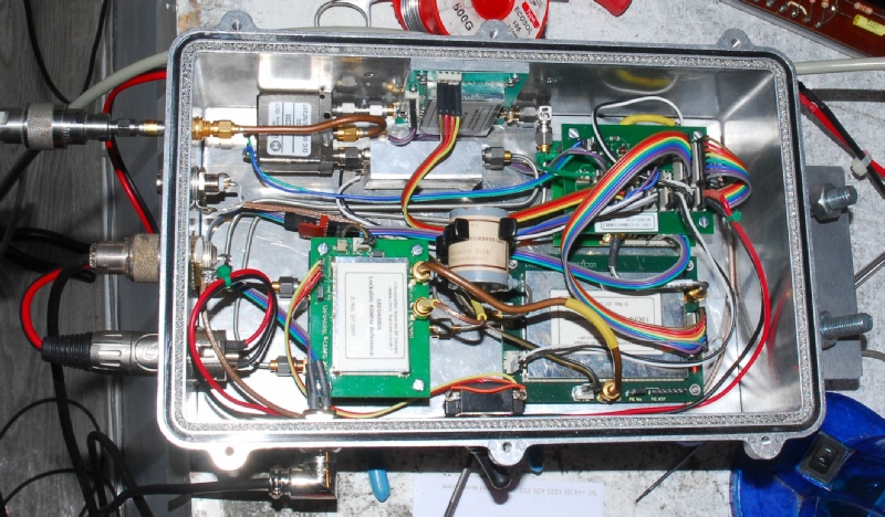
The photograph above is of the final build under test. For added rigidity the relay is now screwed onto a pillar which in turn is glued to the sub-chassis. The reason for this is discussed later. The control cable (PTT) to Alan’s FT817 is by way of a right-angle 4-pin ‘microphone’ connector on the side below the weather-proof switch. Note that this comes into the enclosure rather close to the 40MHz Reference board. This is NOT a design feature but a mistake. Initially the hole for the switch was drilled in the wrong place. This hole was simply re-used for the PTT control. Note the use of ribbon cables throughout. There are NO solder connections to any of Chris’s boards. In fact making any solder connections to Chris’s boards invalidates the warranty.
The PA is secured to the inner wall of the enclosure using screws and double-sided thermal transfer adhesive tape. A nominal heatsink has also been bolted to the outside of the enclosure in the vicinity of the PA.
The PA is secured to the inner wall of the enclosure using screws and double-sided thermal transfer adhesive tape. A nominal heatsink has also been bolted to the outside of the enclosure in the vicinity of the PA.
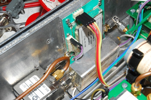
Those with sharp eyes might have noticed the green cable-tie in the previous photograph. When doing final tests on the system I encountered a couple of issues relating to the PA. Unlike all of the other modules, this is constructed on a very thin flexible substrate. This is by design and for reasons that I am not qualified to go into. A down-side of this is the flexibility of the material. I found that weight or lateral force on the SMA launchers caused them to move. This actually caused the output track to fracture requiring repair. This movement also appears to affect the input matching. Hence the green cable-tie … it adds rigidity. It should be noted that Alan’s modules all carry very early serial numbers. I have discussed my findings with Chris who informs me that he is now aware of a tolerance issue which resulted in the launchers’ tendency to move.
This is also the reason for the pillar securing the relay to the chassis … It adds that bit of extra rigidity and ensures that the output launcher on the PA does not move and flex the thin PCB. If there is a flaw in the mechanical layout of this transverter it is in mounting the PA in this way. Anyone attempting this transverter should take every effort to ensure that the SMA connections to the PA do not put extra strain on the launchers and cause the board to flex.
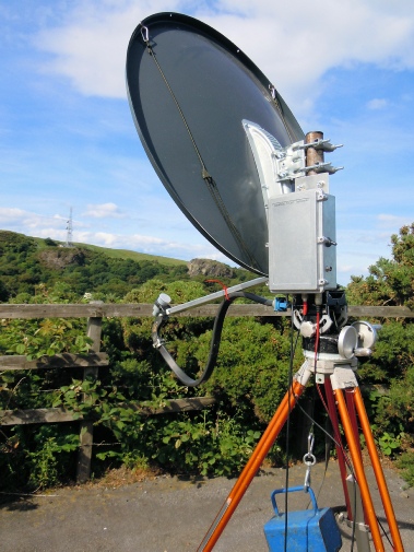
Below is an audio recording of GM3WOJ’s personal beacon as received on this transverter from a location on the side of the Braid Hills in Edinburgh using the setup on the right.
Below is an audio recording of GM3WOJ’s personal beacon as received on this transverter from a location on the side of the Braid Hills in Edinburgh using the setup on the right.