The Racal RA1217
21 minute read
October 2010
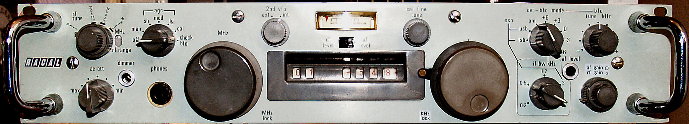
The much maligned RA1217 (the rack-mounting variant of the RA217) was Racal’s first transistorised HF receiver and is for all intents and purposes an RA117 in everything but looks (and perhaps performance). I had been looking for one of these for over a year, to complete my collection of Racal HF receivers from the 50s through to the 90s. I first saw one close up when myself and two others put on a demonstration of Racal receivers for a local radio society. I was mesmerised by the mechanical digital readout to the extent that I was determined to add one to my collection. The first one that came up on Ebay was being auctioned simultaneously with the R1155 that I was fortunate to ‘win’. Then the one pictured above came up for auction. Actually it was one of two, both described as faulty. I was very fortunate to get this one for less than half the price of some that I have seen over the years! The RA1217 is actually rather rare.
It arrived very well packed and after a few safety checks I confirmed that it was indeed faulty, as described. Actually, there was a sticker on the top cover which declared that it was working but with a faulty Calibrator ... But that was over 20 years ago! It was rather grubby, so I set about giving it a good clean. The knobs and front panel cleaned up nicely with soap and water. The BFO shaft (top RH corner) was bent and duly straightened. It had also been ‘dropped’ on its end at some time and the RF input BNC socket was at a strange angle. So that too was straightened. As you can see from the photograph, the MHz Dial Lock is missing. The KHz Dial Lock had no effect. These locks are very clever and work like car drum brakes. When the lever is moved down into the lock position four ‘shoes’ (for want of a better description) extend from the hub. However this was having no effect since there should be a rubber band around the hub which is pushed against the inside of the knob. I simply fitted two suitable elastic bands, one on top of the other to achieve the correct thickness around the hub and the brake now works perfectly. I’m not too concerned about the missing MHz brake since the MHz tuning mechanism has natural detents and as such is not easily knocked ... See the photograph below.
It arrived very well packed and after a few safety checks I confirmed that it was indeed faulty, as described. Actually, there was a sticker on the top cover which declared that it was working but with a faulty Calibrator ... But that was over 20 years ago! It was rather grubby, so I set about giving it a good clean. The knobs and front panel cleaned up nicely with soap and water. The BFO shaft (top RH corner) was bent and duly straightened. It had also been ‘dropped’ on its end at some time and the RF input BNC socket was at a strange angle. So that too was straightened. As you can see from the photograph, the MHz Dial Lock is missing. The KHz Dial Lock had no effect. These locks are very clever and work like car drum brakes. When the lever is moved down into the lock position four ‘shoes’ (for want of a better description) extend from the hub. However this was having no effect since there should be a rubber band around the hub which is pushed against the inside of the knob. I simply fitted two suitable elastic bands, one on top of the other to achieve the correct thickness around the hub and the brake now works perfectly. I’m not too concerned about the missing MHz brake since the MHz tuning mechanism has natural detents and as such is not easily knocked ... See the photograph below.
It is true to say that when Racal produced the RA17 they gave us a receiver that more than made its mark on the market and more than likely paved the way for the company as a manufacturer of high specification communications equipment. Unlike manufacturers like Collins, Racal was actually new to the game, technology was advancing at a fast pace and it was inevitable that transistors were bound to replace thermionic valves. The RA117 was not as some believe, the successor to the RA17L. The RA117 was conceived to satisfy an Admiralty requirement and was actually built alonside the RA17L. At the end of the day, Racal really only made one valve-based receiver, albeit in many ‘flavours’.
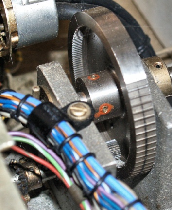
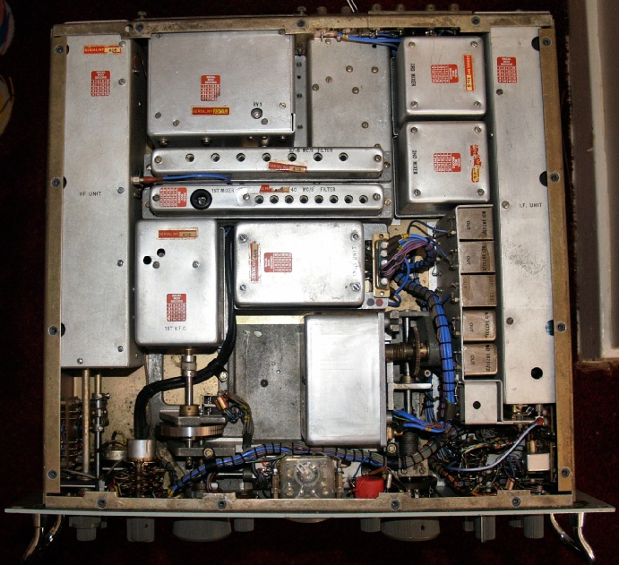
The successor to the RA117 was the RA1217 and it is debatable if there were actually any performance improvements in the design. When you lift the lid the first thing that strikes you is the modular construction. Each module can easily be identified with its predecessor counterpart. It is clear that Racal simply took the ‘elements’ within the RA117 and designed transistor-based versions. However the RA1217 still retains some of the aspects of its predecessor in that the chassis is still largely of cast aluminium which offers a modicum of rigidity, although this chassis is now surrounded by a steel frame. Hats off to Racal for going for a digital frequency readout! The implementation of which is a masterpiece of engineering. The KHz mechanism is similar to that in the RA117, but I really love the way the drive cog on the MHz tuning shaft interfaces with teeth on the inside of the main gear. The outside of this gear is machined so as to produce a ‘natural’ detent per MHz.
The successor to the RA117 was the RA1217 and it is debatable if there were actually any performance improvements in the design. When you lift the lid the first thing that strikes you is the modular construction. Each module can easily be identified with its predecessor counterpart. It is clear that Racal simply took the ‘elements’ within the RA117 and designed transistor-based versions. However the RA1217 still retains some of the aspects of its predecessor in that the chassis is still largely of cast aluminium which offers a modicum of rigidity, although this chassis is now surrounded by a steel frame. Hats off to Racal for going for a digital frequency readout! The implementation of which is a masterpiece of engineering. The KHz mechanism is similar to that in the RA117, but I really love the way the drive cog on the MHz tuning shaft interfaces with teeth on the inside of the main gear. The outside of this gear is machined so as to produce a ‘natural’ detent per MHz.
So what is it about the RA1217 that rendered it so dislikable? I have even heard it referred to as the ‘disasterous 1217’ . In terms of facilities, it differs very little from the RA117. However there are ergonomic differences, the most obvious being the reversal of the main tuning knobs and I can see how if you were used to the RA17 configuration how a reversal would have you spinning the MHz knob instead of the KHz one. Also, the preselector and attenuator controls are on the left as opposed to the right, so that might be taken as inconvenient. I have heard it said that the RA1217 suffered badly from RF overload problems. This is probably true and partially due to fact that transistor designs from that era (developed in the 1960s) were prone to such problems. However, whereas I agree in part with this prognosis, I have found that if the AGC circuits (there are actually two) are not set up correctly, then you will find that even switching in all sections of the input attenuator will not have much effect on very strong broadcast stations. Something else which I have noticed is that making it only three and half inches high might have resulted in some mechanical instability. I have found that it does flex very slightly when lifted from the front. What appears to happen is the D-type connector on the IF unit partially disconnects resulting in the AGC line being disturbed and hence the RF gain temporarily changes before the AGC re-asserts.
As I previously mentioned, my RA1217 was advertised as faulty. The fact that the calibrator was known to be faulty was no guarantee that there were no other faults either. When I switched it on, it was clear that the audio stage was working since there was a light hum in the headphones (the RA1217 has no internal loudspeaker). None of the three lightbulbs were lit and I traced the cuase of this to not one, but two breaks in the wire which daisy-chained the bulbs together. Oddly, this is a thin coax.
For some reason, after getting the bulbs to light, the mains fuse blew. This turned out to be a 1A fuse, but should have been a 250mA one. The PSU in the RA1217 is interesting and yet simple. It can be set to accept 24V DC or AC (120V or 240V). Each of the 120V windings has a 22nF capacitor across it. I suspect that one of these capacitors (Hunts tubular) was breaking down, so I replaced them both and replaced the fuse with one of the correct rating ... Problem solved!
As with the RA17, the alignment procedure starts with the 3rd IF, but like the RA117, this is 1.6MHz. I connected my 9301 to the 1.6MHz output on the rear panel and fed a suitable signal in at the input to the IF Module. All the cores in the 1.6MHz stage were out of alignment ... Someone had been twiddling. The IF Module is also home to one of the two AGC stages and it clearly had a fault. I quickly found a broken PCB track under the board which when repaired, enabled me to progress through more of the procedure ... A procedure made slightly confusing since there is an error in the manual relating to initial settings. Having got two out of the three AGC settings to ‘make sense’ I moved on to the detectors and then to the BFO section. Everywhere I went, the twidler had been before me!
The RA1217 has seperate crystal controlled oscillators for USB and LSB recovery and a 5-setting variable BFO for CW reception. The latter was not performing as per the manual and it appeared that one of the SSB oscillators was running all the time, even when in AM mode. It also looked like one of the oscillators was slow to start. There was a white address label on the lid of the IF module. When I removed the label, someone had written on the lid ‘faulty, suspect LSB crystal u/s’. However, the module was more or less working but the receiver was still essentially dead ... So I turned my attention to the RF module.
Where the IF module occupies the right hand side of the receiver, the RF module occupies the entire left side. A quick glance told me that the fault could be one of several things ... The spark gap, the 1A fuse!, the attenuator or the main PCB itself. However the fault was much simpler. The manual asked me to remove the output cable and connect the RF voltmeter to the connector. On examining the connector it was clear that inside the RF module NOTHING was connected to it! There was however a short blue wire from a pin on the PCB nearby which appeared to go under the PCB. I pulled at it with my tweazers and found it to be ‘free’. I can see how a wire can break, but to get tucked under the PCB? ... Someone had definitely been at this receiver. On reconnecting the wire and attaching an aerial to the RF input connector, the RA1217 burst into life. It was not the most sensitive of receivers but it was a start. Like the RA17 series, there are two multipole LC filters. The 40MHz filter is over-coupled and must NOT be adjusted without suitable test equipment. I have a network analyser for this purpose. The 37.5MHz filter, in contrast, is loose-coupled, and provided you have a received signal, it is possible to adjust this filter for maximum output at 1.6MHz (rear panel connector). The retaining screws for the 37.5MHz filter were missing, which was ominous, but the filter tuned up nicely. I have not found it necessary to adjust the 40MHz filter.
Now that we were now receiving signals, I returned to the IF module and the somewhat ‘disfunctional’ AGC circuit. The problem was that although I could set up the AGC voltage as per the manual for the fast and medium hang-times, and the AGC worked on these settings, the AGC voltage jumped to over 5 volts when the long hang-time was selected, rendering most strong signals unreadable. Also, the S-meter didn’t behave properly and the adjustment potentiometer actually changed the AGC voltage. Closer examination of the AGC board revealed an off-board 50uF electrolytic capacitor mounted on pins. Curiously, both pins were at ground potential (0V). By the looks of things this capacitor had been wrongly wired since manuffacture since there was absolutely no evidence that the pin that it should have been soldered to had ever seen solder. Moving the lead over to the correct (adjacent) pin did not however rectify the AGC problem. Then I found a reference in the manual to setting up the RF unit AGC voltage. This is done by way of a potentiometer tucked away under the main chassis, accessible through a panel underneeth the set. This had been set for an AGC voltage far lower than the specified 4V. I reset it to 4V and the gain of the receiver increased dramatically. Now back to the IF module ... Again.
Interestingly, now that the RF unit AGC was correctly set, the S-meter now actually functioned and the adjustment potentiometer no longer had an adverse effect on the AGC and consequentially, the receiver gain. After eliminating almost all possibilities, I concluded that the problem with the long hang-time setting had to be something to do with the timing capacitor (6.4uF). It did look like it was trying to escape from it’s can! So I replaced it with a newer 4.7uF one. However the voltage was still ‘stuck’ high. I then decided to be radical and replaced it with a 1uF capacitor ... BINGO! But the hang time was too close to that of the medium setting. I found that a 2.2uF capacitor was the maximum that the circuit could handle ... Weird or what? Finally I located a dry joint on the AGC board which was causing the AGC to fluctuate.
The suspect SSB oscillator crystal refered to in the hand-written note on the IF module lid turned out to be a faulty decoupling capacitor. Selection of the respective oscillators is implemented by way of diode switching. Here, there looks like there has been a problem with noise pick up and an extra decoupling capacitor (0.22uF) has been added off-board for each of the two oscillators. One of these was more resistor than capacitor to the effect that even when LSB was not selected, current was flowing through the capacitor and forward biasing the diode and as a result the LSB oscillator was still running. Replacing the errant capacitor sorted that issue!
Previously, because the LSB oscillator had been running constantly, it had been impossible to measure the frequency of the CW BFO. This is the variable BFO with 5 preset offsets. This is an intriguing circuit in that it takes a feed from the master 1MHz oscillator and mixes it with a 600KHz variable source. However, this is one area of the RA1217 design which ‘lets the side down’ big style. The 600KHz oscillator is tucked in behinfd the front panel for obvious reasons, but access to the adjustment core and 4 trimmer capacitors is obscured by the D-type connector on the IF module. Secondly, the buffer amplifier is very difinitely an after-thought and is mounted on a separate board next to the oscillator. Switching through the 5 preset offsets it was clear that none of them were correct and although I could, at a push, get a trim-tool in to adjust some of the capacitors, the errors were simply too great. So I made a careful note of the wire colours and associated pins and removed the two boards. I re-built the two boards on an external chassis complete with a suitable variable capacitor. To my amusement, it looked like someone had used a drill-bit rather than a trim tool on the oscillator core ... The slot was non-existent! When I refitted the two boards into the set, the frequencies were understandably different, due to wire lengths and general proximity issues. However, as before, the trimmer capacitors did not appear to be having the desired effect. Only then did I notice that the ends of the wires from the oscillator board to the switch did not look ‘original’ ... Someone had previously removed the boards but had removed the entire wire harness and put the wires back on the switch in the wrong order. So much for noting which wire came from where! Referring to the manual, I carefully rewired the switch correctly and found that only minor adjustments were required to achieve the nominal offsets of +/- 6KHz, +/- 3 KHz and 0KHz. With the BFO now working I made a final adjustment to the BFO mixer in the IF module. Now all that was left to sort out was the faulty calibrator circuit.
As mentioned previously, I knew from the start that the calibrator was faulty. The calibrator circuit is a transistorised rendition of the traditional RA17 circuit. It occupies the same PCB as the master 1MHz oscillator and is contained in the screened metal enclosure in the centre of the receiver. One thing that I have not mentioned before is that my RA1217 is an early model with serial number 406. I am not sure if it is because this is an early model, but the other board in the 1MHz unit which carries the 1MHz buffer amplifiers (input and output) is not a printed circuit but simply a sheet of GRP with all the components mounted between pins on the top side and interconnecting wires on the underside. Anyway ... Clearly the calibrator had stopped working and our friend, the twiddler had been at work. The transformer cores relating to the calibrator had obviously been sealed with a particularly nasty core-locking compound that I was familiar with (I’m ex-Racal). Someone had succeded in moving one of the cores but had broken it in the process. Two of the three tansformers are by Cambion and are cylindrical with an ‘external’ ferrite. That is, the ferrite is actually a ‘cup’ which is moved up and down over the transformer windings. I was able to remove the transformer, dismantle it and successfully reasemble the ferrite using super-glue. This repair worked up to a point, but I was unable to achieve the correct waveform as given in the manual. It was very obvious that the circuit was not resonaing at the desired frequency of 900KHz but at a much lower frequency. Exactly what the fault was, I’m not sure, because the ferrite eventually broke again. I had verified that the resonating capacitor was the correct value and had tried reducing the value to no avail. I even tried changing the diodes and only succeeded in making it worse. But with the transformer now u/s and with little hope of finding a replacement I concluded that an alternative calibrator circuit was required.
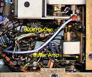
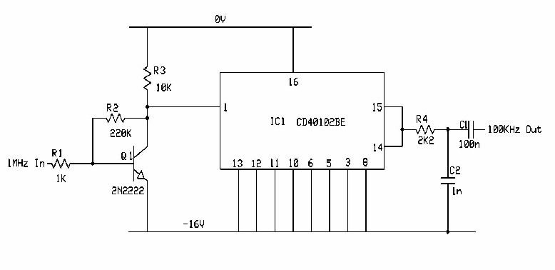
It is very likely that the calibrator circuit was unreliable and/or difficult to set up since later models of the RA1217 employed a single integrated circuit to generate the 100KHz signal. For some reason the circuit diagrams are in the User Manual and the Board Layouts and Items Lists are in the Maintenance Manual. Since I have managed to download two versions of the User Manual I actually have the schematic for the later ‘1-chip’ Calibrator. But since I cannot find anything other than Issue 1 of the Maintenance Manual, I can only guess that the chip is an ECL type. Not to worry though! It’s only a divide-by-ten circuit. I removed most of the components from the PCB relating to the calibrator with the exception of R14, R15 and D6. Something else about the RA1217 which takes a bit of getting used to is the fact that at first glance all the circuit diagrams appear to be upside-down. This is because as with a lot of early solid-state equipment, most of the transistors are PNP. As a result the supply rail to all the modules and PCBs is minus 16V. Below is the circuit which I eventually arrived at. The transistor is a 2N2222 (NPN) and the IC is a CD40102BE CMOS BCD divider which can handle supply rails of up to 18V. The input is fed direct from the original coax from the buffer amplifier board. The output (pins 14 and 15) on the IC is fed to the junction of R14, R15 and D6.
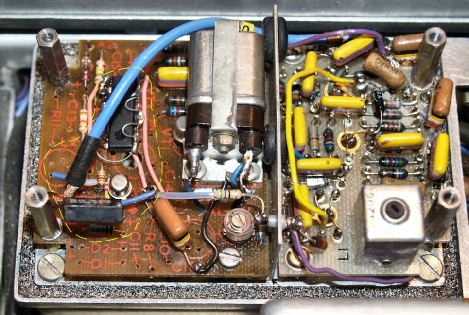
The photograph on the left shows the new calibrator in place, outlined in yellow with the CD40102BE mounted ‘dead-bug’ style with double-sided tape. The large black capacitor is part of the original circuit and is just there to decouple the minus 16V line. Interestingly the original 56 ohm resistor in series with the supply to the calibrator (just above the trimmer capacitor in the photograph) was swollen and measured only 32 ohms ... So obviously something had failed in the original circuit and incurred excessive current drain, enough to ‘cook’ the resistor. With reference to the photograph, several of the ‘colourful’ capacitors on the buffer amplifier board were not actually soldered to their respective pins! This and the capacitor on the AGC board that was soldered to the wrong pin makes me wonder if Racal had a temporary quality control problem during production.
So, how does the RA1217 perform? Very well, actually. With all the bad publicity that has attached itself to the type, I was fully expecting something mediocre at best. Instead I was pleasantly surprised. I live about 10Km from the local Medium and Long Wave transmitters and the built-in attenuator is more than capable of pitching the strongest of received AM signals into the range of the AGC circuitry. And the manual RF gain control is a more than adequate alternative to AGC. Agreed, the signal to noise ratio is clearly not as good as the RA17L and nowhere near that of my RA1772 ... But in terms of sensitivity it is just as sensitive as the 1772! ... Which I did not expect.
As previously mentioned, my RA1217 is an early model and so has the 1W audio board fitted which is ideal for driving an external loudspeaker. It is also fitted with a full complement of crystal filters ... 8KHz for AM, 3KHz for SSB and 1.2KHz, 500Hz and 200Hz for CW reception.
Is there anything I dislike about the RA1217? I can honestly say that I cannot not like the the 1217. Everything works. The pre-selector is sharp. The tuning is smooth. The stability is superb and typical of the Wadley Loop design. When my daughter was home from St. Andrews University recently, I proudly, tongue-in-cheek, showed her my new digital-read-out receiver. When she saw the mechanical digits her reaction was “Oh that’s so cute!” and I tend to agree since they remind me of old petrol pumps and it is perhaps this feature that I find most endearing.
OK, the RA1217 was definitely not up to the performance of the RA117 that it was designed to replace, but this was Racal’s first transistorised HF receiver at a time when some of their competitors were still manufacturing valve receivers. It is likely that lessons were learned with the RA1217 that eventually paved the way for the legendary RA1772.
If there is one disappointing feature, and I say this with tongue firmly planted in cheek ... You cannot use it to heat the radio room! Whereas the RA17, RA1772, RA1792 and RA3701 all output massive volumes of heat, the little RA1217 remains cool, even when left switched on all day.
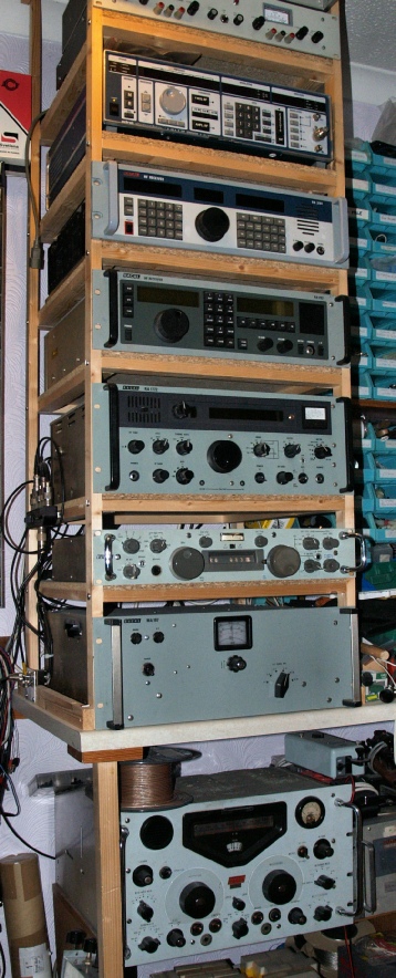
So there it is, on the right, sandwiched between the MA179C and the RA1772. The collection is complete (for now!). The equipment just above the RA3701 is not a receiver, but is an Adret 740A signal generator. And before anyone comments on the relatively small leg at the corner of the bench ... The rack is actually screwed to the ceiling and there is a very substantial support just out of shot to the right.
March 2017: I am indebted to Patrick ON6XS for very kindly supplying me with a dial-lock mechanism for the MHz dial.
As previously mentioned, my RA1217 is an early model and so has the 1W audio board fitted which is ideal for driving an external loudspeaker. It is also fitted with a full complement of crystal filters ... 8KHz for AM, 3KHz for SSB and 1.2KHz, 500Hz and 200Hz for CW reception.
Is there anything I dislike about the RA1217? I can honestly say that I cannot not like the the 1217. Everything works. The pre-selector is sharp. The tuning is smooth. The stability is superb and typical of the Wadley Loop design. When my daughter was home from St. Andrews University recently, I proudly, tongue-in-cheek, showed her my new digital-read-out receiver. When she saw the mechanical digits her reaction was “Oh that’s so cute!” and I tend to agree since they remind me of old petrol pumps and it is perhaps this feature that I find most endearing.
OK, the RA1217 was definitely not up to the performance of the RA117 that it was designed to replace, but this was Racal’s first transistorised HF receiver at a time when some of their competitors were still manufacturing valve receivers. It is likely that lessons were learned with the RA1217 that eventually paved the way for the legendary RA1772.
If there is one disappointing feature, and I say this with tongue firmly planted in cheek ... You cannot use it to heat the radio room! Whereas the RA17, RA1772, RA1792 and RA3701 all output massive volumes of heat, the little RA1217 remains cool, even when left switched on all day.
So there it is, on the right, sandwiched between the MA179C and the RA1772. The collection is complete (for now!). The equipment just above the RA3701 is not a receiver, but is an Adret 740A signal generator. And before anyone comments on the relatively small leg at the corner of the bench ... The rack is actually screwed to the ceiling and there is a very substantial support just out of shot to the right.
March 2017: I am indebted to Patrick ON6XS for very kindly supplying me with a dial-lock mechanism for the MHz dial.