The Racal RA137A
9 minute read
August 2015
Last month I picked up a couple of very sorry looking RA137As. Both were incomplete and looked as if they had been stored in a chicken shed! Although both were missing the rectangular tuning bezel, a quick glance over them convinced me that I had a good chance of getting a working converter from the two ‘wrecks’. Using what I took to be the date codes, one was assembled in January 1963 and the other in June 1964. The older of the two was definitely in a worse state. A large part of the Perspex tuning cursor was missing and the rotating ‘drum’ was seized. An interesting point here is that this unit used an unusual drive cord arrangement for turning the drum where it looks like the drum is spring-loaded and a cord is used to ‘wind it back’. Despite it’s shocking condition the front panel on this unit was the better of the two so I decided to swap the panels over.
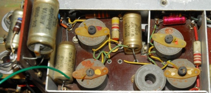
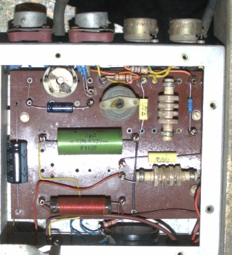
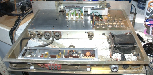
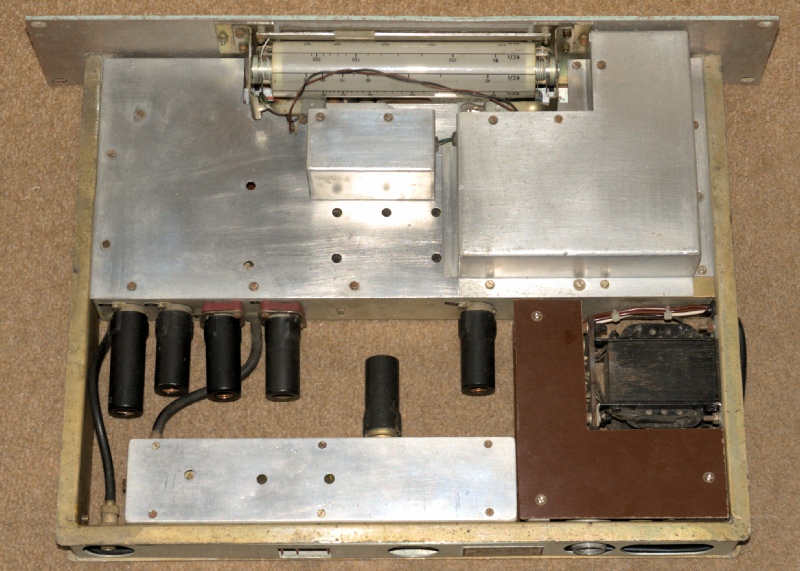
Having decided to use the newer of the two RA137As as the basis for my re-build I removed the top and bottom covers from the RF compartment. The photograph on the left is the 1MHz LP filter on the output of the RF amplifier. Note the loose ferrite. What has happened here is a result of deterioration of the threaded plastic former which also doubles as the means of securing the inductor to the board. The plastic has snapped where the nylon (or plastic) screw held it down. This situation applied to all but one of the cores in this picture and another two in the Pre-Selector compartment. Luckily I was able to salvage enough parts from the ‘donor’ unit to secure all the inductors.
Unlike the RA17, the RA137 is not complex. It consists of an RF amplifier with a switchable preselector, a double balanced mixer and a cathode-follower output stage. The 2MHz Local Oscillator is derived from the 1MHz output from the RA17 by way of a simple harmonic generator. See the image below.
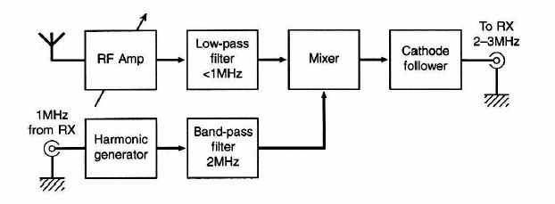 RA137 functional block diagram
Despite it’s simplicity, the RA137A proved to be an annoyingly awkward unit to work on … largely due to the fact that the valves are mounted end-on to the double sided tag boards. Consequently, the underside of each socket is partially obscured by the lip of the enclosure.
And just to make that point ...
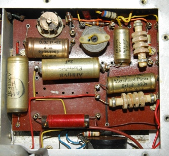
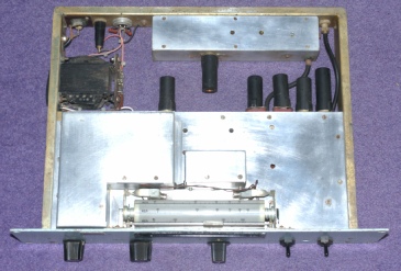
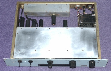
The photographs above show one side of the main RF board before and after refurbishment. Note how the valve bases are obscured. Note also the two anti-microphony bases for the two 6F33s.
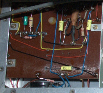
On the right: The other side of the same board. This photograph was taken during fault finding with the RA137A in-situ, on top of my RA17L … hence the grey coax top left.
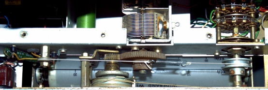
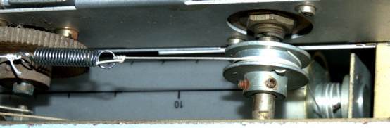
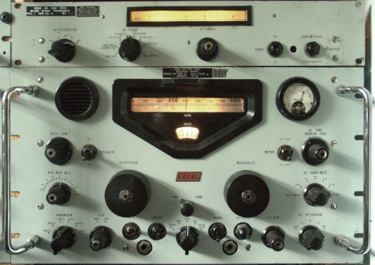
The coverage of the RA137 is 12.5KHz to 980KHz. Like in the RA17 where the preselector breaks the coverage into 6 concatonated ranges, the preselector in the RA137 also divides the coverage into 6 ranges. There are also 2 ‘Wideband’ positions, one of which includes a 500KHz Low Pass Filter. The scales for these ranges are printed on a mylar sheet which is wrapped around a hollow Perspex drum which is turned by way of a clever drive cord arrangement. The spindle for the preselector switch carries an aluminium spool, the diameter of which is the same as the spindle on which the drum rides. However, the cord was missing. Thus, I had to first figure out the routing for the cord. It was also important that the scale visible in the window matched the range selected. What made this a challenge was that in this, the newer of the two RA137As, the switch did not appear to have an end-stop! Although it was apparent that the drum spindle ends were ‘threaded’ to provide a channel for the cord to run in, it was not clear how the cord was secured to the spindle. The outer ends of the spindle have a small hole which goes right through so I figured that this formed part of the anchor. Although I got the drum turning at my first attempt, my routing did not make correct use of the spool and did not have the anti-backlash spring. Thanks to Brian Goldsmith in Australia, who kindly emailed me some detailed photographs, I was able to re-string the drive cord correctly. I used short lengths of 16swg wire to anchor the drive cord into the holes at either end of the drum spindle. See the photographs above. Starting at the end nearest the spool, the first cord is wound around the spindle several times, keeping to the grove provided. It is then wound onto the drive spool at least once. Then comes the clever bit. The cord is then fed through the hole in the rear wall of the spindle and back through a hole close to the centre of the spool before being fed back onto the spool through a hole in the front wall of the spindle. It is then wound at least once around the spindle before being tied to one end of the spring. The second cord starts at the other end of the spring goes over the pulley and then onto the grooved spindle at the other end of the drum where it is wound on several times and secured in the same manner as the other end.In my case there was a bit of trial and error in getting the position of the spring right and getting the scale to match the selected range.
With the drum now synchronised to the switch and most of the resistors and capacitors replaced, it was then time to start reassembling RA137A N0717. All the aluminium surfaces required extensive cleaning and rubbing down with wire wool. Also, for some reason some of the wiring had been cut out. This was cheekily replaced with the same wiring culled from RA137A N264. Both RA137s were devoid of valves but since I am in the business of refurbishing RA17s I always have a good stock of valves and the RA137 uses valves that are common to the RA17 series, with the exception of the 150C2 stabiliser, but fortunately I had three of these in stock.
N0717 was missing the aluminium rear panel so I fitted the one belonging to N264. The serial number is wrong, but that is a tiny detail.
The mains transformer in the RA137 only supplies the heater voltage. The HT is derived from the host RA17. Before connecting up to my RA17L, I tentatively powered the RA137 from an external variable HT PSU. The prime reason for this was to verify the integrity of the 150C2 stabiliser. As it was, 2 out of the 3 that I had proved to be faulty. However, N0717 worked rather well right from the start and the tuning scale accuracy was not too far out either … despite the fact that I had estimated the relationship of the cursor position with the amount of capacitor meshing! Whereas adjusting the level of 2MHz Local Oscillator signal is very straightforward, balancing the Double Balanced Mixer is another story. Ideally the two CV2209s (6F33s) should be pre-matched. The hole between the two front panel toggle switches gives access to the balancing control, and initially I found that the desired null could not be obtained. Checking the two 6F33s on my valve tester, one was found to have a much higher (than spec.) mutual conductance. Going through my collection I eventually found two which were closely matched. Even then it was still not possible to balance the mixer perfectly as per the manual until I swapped the valves over. Having done that, a deep null was obtained. This is best done once the valves are fully warmed up otherwise the balance point drifts.
I have often pondered seeking an RA137A to complement my RA17 or RA17L but until now I had never taken the notion seriously. The RA137 is actually a highly competent VLF/LF converter with many VLF signals coming in on my Top-Band inverted-V. From my location about 20Km West of Edinburgh, I can clearly hear NDBs from Edinburgh (2), Glasgow, Dundee and Prestwick. The preselector could do with a bit of realigning such that the calibration matches the RA17L but at the moment I will just enjoy playing with my new toy.
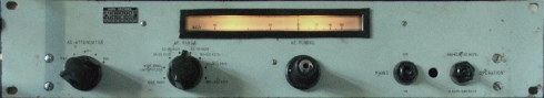
Note that my RA137A now has a tuning bezel. This is a home-made affair. A strip of Perspex sheet has been glued to the rear of the front panel whilst the black bezel is made from plastic ‘lipping’, originally white, but sprayed black and held in place with double-sided tape. The small ‘lip’ fits very neatly into the aperture in the front panel.
I have often pondered seeking an RA137A to complement my RA17 or RA17L but until now I had never taken the notion seriously. The RA137 is actually a highly competent VLF/LF converter with many VLF signals coming in on my Top-Band inverted-V. From my location about 20Km West of Edinburgh, I can clearly hear NDBs from Edinburgh (2), Glasgow, Dundee and Prestwick. The preselector could do with a bit of realigning such that the calibration matches the RA17L but at the moment I will just enjoy playing with my new toy.
Note that my RA137A now has a tuning bezel. This is a home-made affair. A strip of Perspex sheet has been glued to the rear of the front panel whilst the black bezel is made from plastic ‘lipping’, originally white, but sprayed black and held in place with double-sided tape. The small ‘lip’ fits very neatly into the aperture in the front panel.
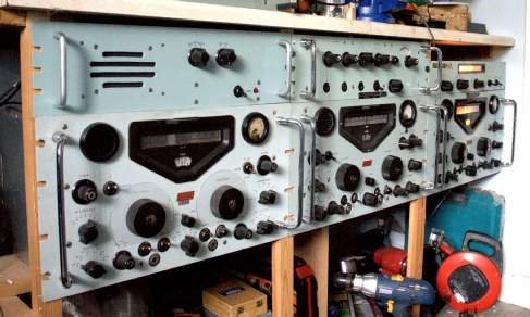
I have swapped my RA117 and RA17L. This actually makes a lot of sense since the RA117 now sits under the RA218, which was specifically designed to complement it. Because of it’s low profile, the RA137A fits neatly above the RA17L at the far right.
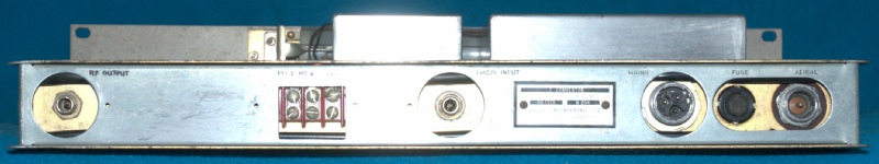
Finally … it seemed prudent to fashion a couple of protection plates to cover the otherwise exposed mains wiring. Curiously, it looks like these two plates were either only fitted on early models or when requested. The plates are screwed to three U-shaped brackets. The two at the rear are secured by existing screws whilst the bracket on the main RF enclosure makes use of a pre-existing hole.
Ironically, when preparing to fit the plates, I gave myself a nice ‘belt’ when I accidentally touched the mains fuse with my left hand whilst holding the chassis with my right hand. It’s been a while since I’ve done that!!
Ironically, when preparing to fit the plates, I gave myself a nice ‘belt’ when I accidentally touched the mains fuse with my left hand whilst holding the chassis with my right hand. It’s been a while since I’ve done that!!