Updating my G3RUH GPSDO
3 minute read
August 2016
Inspired by the design of the Rapco 1804P9 GPSDO, I decided to look at ways of enhancing my home-brew GPSDO wich is based on a design by James Miller, G3RUH. Since I now own a professional GPSDO, I figured it wouldn’t hurt to strip down my old one then re-build it as a viable back-up. See here for the original article by G3RUH.
As previously mentioned, following the failure of the Isotemp 134-10 OCXO (twice!), my GPSDO has since been running a much smaller OCXO by Isotemp, a 143-141. Unlike the larger 134-10 which ran from 13V and delivered a 2V p-p sine-wave into 50-ohms, the 143-141 runs from a 5V supply and the 10MHz output is TTL … Not ideal for some applications.
As previously mentioned, following the failure of the Isotemp 134-10 OCXO (twice!), my GPSDO has since been running a much smaller OCXO by Isotemp, a 143-141. Unlike the larger 134-10 which ran from 13V and delivered a 2V p-p sine-wave into 50-ohms, the 143-141 runs from a 5V supply and the 10MHz output is TTL … Not ideal for some applications.
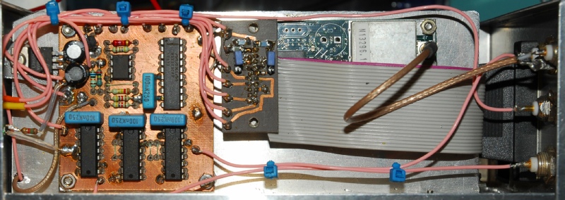
The photograph above shows the GPS receiver on the right with the home-brew PLL board on the left. The 8-pin IC is for amplifying the control voltage to a level compatible with the 134-10 OCXO. This is not required when the OCXO is a type 143-141. In fact the output of the amplifier is too high for the latter. I could have changed the value of one of the resistors so that the gain was unity but it was simpler just to take the control voltage from the input to the op-amp; tacking the wire onto the junction of R1 and C1. The two 4K7 resistors on the output of the OCXO have been isolated since the output of the 143-141 is TTL. James Millar has improved the design of this board since I built it, so there are some differences.
My plan was to re-build the GPSDO such that it had multiple 10MHz outputs, each delivering at least 2V p-p into 50 ohms … And I would base my design on the output stages in the Rapco 1804 … And I might as well include a suitable PSU to power the GPSDO at the same time. The PSU would need to provide +/-12V for the line drivers, +5V for the OCXO and nominally +12V for the GPS receiver and the PLL board.
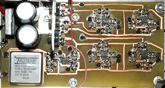
LM6181s are used for the 50R drivers. This is a current-feedback amplifier providing very high slew-rate, bandwidth and high output current. I found 20 on Ebay for a mere £15. The fact that these were surface-mount devices was not a problem and besides, I was up for the challenge! A three-stage R-C filter converts the 10MHz TTL into a pseudo-sine-wave. This is then amplified before being fed to the four parallel output stages. The output of each stage can be set independently to deliver 2V p-p into 50 ohms. The mains transformer has two 15V output windings … ideal for a split-rail PSU. However this incurred a temperature problem. The OCXO runs from a single 5V rail and draws at least 500mA at switch-on. This drops when the OCXO has reached optimal temperature and is well within the capability of a 7805 regulator. However the raw DC from the bridge rectifier is a shade over 20V, meaning that the regulator was having to dissipate 7.5W. The heat-sink was getting very hot indeed. There are two ways to deal with this. Use a larger heat-sink, or drop the input voltage. I decided on both! A 2SC3281 and an 11V Zener diode act as a pre-regulator, dropping the voltage at the input of the 7805 down to about 10.5V … effectively halving the power dissipated in the regulator. The same 10.5V line also supplies the GPS RX and the PLL board. The PCB layout is double-sided with some of the DC distribution on the underside.
My plan was to re-build the GPSDO such that it had multiple 10MHz outputs, each delivering at least 2V p-p into 50 ohms … And I would base my design on the output stages in the Rapco 1804 … And I might as well include a suitable PSU to power the GPSDO at the same time. The PSU would need to provide +/-12V for the line drivers, +5V for the OCXO and nominally +12V for the GPS receiver and the PLL board.
LM6181s are used for the 50R drivers. This is a current-feedback amplifier providing very high slew-rate, bandwidth and high output current. I found 20 on Ebay for a mere £15. The fact that these were surface-mount devices was not a problem and besides, I was up for the challenge! A three-stage R-C filter converts the 10MHz TTL into a pseudo-sine-wave. This is then amplified before being fed to the four parallel output stages. The output of each stage can be set independently to deliver 2V p-p into 50 ohms. The mains transformer has two 15V output windings … ideal for a split-rail PSU. However this incurred a temperature problem. The OCXO runs from a single 5V rail and draws at least 500mA at switch-on. This drops when the OCXO has reached optimal temperature and is well within the capability of a 7805 regulator. However the raw DC from the bridge rectifier is a shade over 20V, meaning that the regulator was having to dissipate 7.5W. The heat-sink was getting very hot indeed. There are two ways to deal with this. Use a larger heat-sink, or drop the input voltage. I decided on both! A 2SC3281 and an 11V Zener diode act as a pre-regulator, dropping the voltage at the input of the 7805 down to about 10.5V … effectively halving the power dissipated in the regulator. The same 10.5V line also supplies the GPS RX and the PLL board. The PCB layout is double-sided with some of the DC distribution on the underside.
 Click the above photograph for a pdf of the circuit diagram
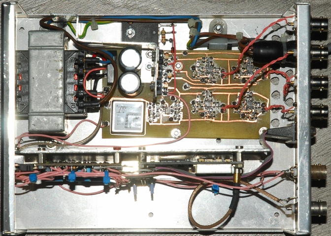
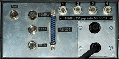
Twisted pairs are used to connect each of the 10MHz outputs to their respective BNC connectors on the rear panel.
So now I have a back-up 10MHz GPSDO!
So now I have a back-up 10MHz GPSDO!