Power Amplifier Type MM420
23 minute read
October 2023
Back in April this year I was tasked with investigating the replacement of the output transistors in the Racal MM420 Power Amplifier module. Not so much how to replace them, but what were the 'rules' to be followed? ... given that the output stage is a pair of 'quads', each consisting of two pairs ... eight transistors in total. And that's only the output.
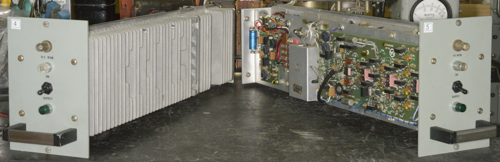
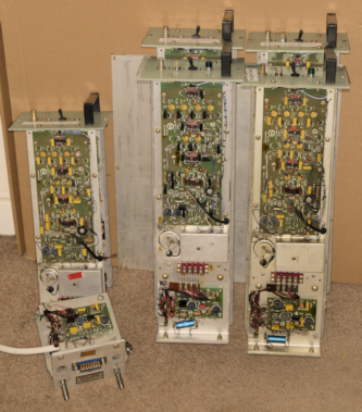
Two MM420 Power Amplifiers
Racal stopped providing support to the end user many years ago, at a time when many users would have moved onto the 3700-series kit in the 1990s. I am reliably informed that there are literally hundreds of MM420s still in active service ... presumably in TA.1813s and the like ... and as expected, owing to the way they are designed, and due no doubt to the scarcity of certain components, the users are now struggling to maintain them. Hence why someone was tasked with investigating just how to go about replacing the RF devices on the High-Level board.

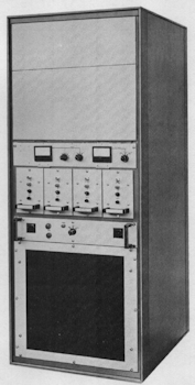
TA.127
Unfortunately the advent of semiconductors did not mean that one valve could be replaced by one transistor. The RA1217 which can be considered a transistorised RA117 is a case in point. As far as I am aware the TA.1800 series was Racal's first foray into semiconductor-based power-amplifiers designed with long duty cycles in mind. Before that you had the TA127 ... an all-valve 1KW HF transmitter with an MA79G as the chosen RF source. The 1KW output came from a TA.99 amplifier which achieved this by way of only six valves! And it would do this with only 100mW of drive too.
Way back in 2001 I built myself a 300W HF Linear Amplifier, based on a design by Helge Granberg at Motorola. Originally published as AN758 back in 1981, this amplifier employs a matched pair of Motorola MRF428 bipolar transistors running from a 48V supply. In contrast, the Racal MM420 is limited to 125W, employing a five-part drive chain involving no less than 18 transistors. The first eight of these run from a 20V rail and the final ten are supplied by a 30V rail. It is worth noting here that Granberg's design requires a nominal drive of 10W whilst the MM420 will comfortably deliver 125W with as little as 10mW of drive.
TA.1813
The gain stages in the MM420 are spread over two boards, with the Low-Level board delivering a nominal 2W of drive into the High-Level board. While Granberg's design operates in Class-AB, all the gain stages in the MM420 are operated in Class-A with the exception of the Grounded-Base push-pull driver-pair on the High-Level board, which operates in Class-B. In Granberg's amplifier, biasing, and thus operating mode, is taken care of by way of a ubiquitous MC1723 regulator and pass transistor. A second transistor is employed as a spacer/temperature compensating P-N junction. I fully expected the MM420 to be biased in a similar way. Not so! Here, biasing of the devices on the High-Level board is set using nothing more than silicon diodes and resistors ... crude but effective and reliable. Grandberg's amplifier is generally robust, thanks to the MRF428s, but all other safety measures have to be implemented by the user. In my case, I designed over-voltage and over-current protection into the PSU. The MM420 takes protection to a whole new level.
Each MM420 comprises the following:-
MS440 Stabiliser Module, which includes the PS313 Regulator Board.
and an MM320 RF Amplifier Assembly comprising the following:-
PS314 or PS351 Low-Level Board.
PS315 High-Level Board.
PS316 VSWR Board.
PS251 Protection Board.
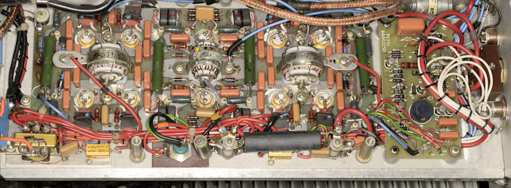
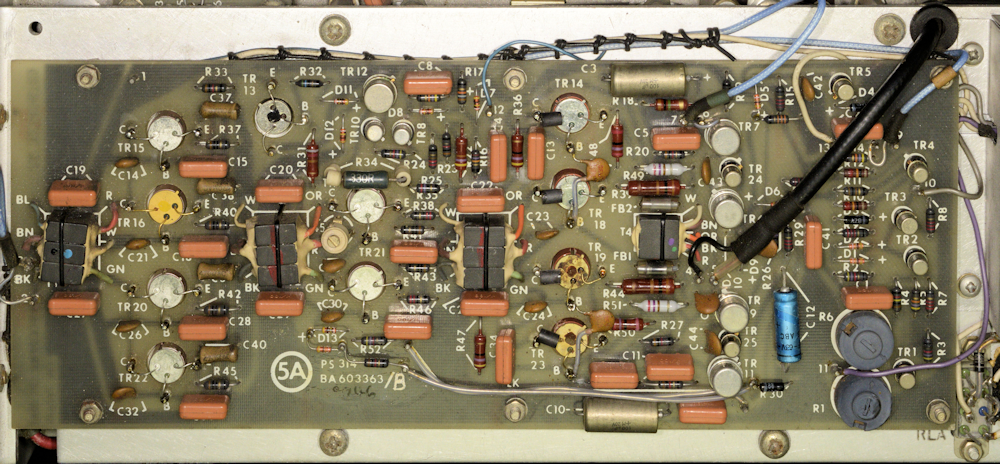
MM420 High-Level board with PS251 Protection Board on right
The DC current in the 30V line to the High-Level board is monitored by measuring the voltage across a pair of 0.1-ohm resistors. Additional monitoring is accomplished by way of a current transformer (not fitted on early versions of the MM420). Should this current exceed approximately 15A, the ALC will operate. Some Long-CR (slower ALC) modules have a multiturn potentiometer and Zener diode connected between the current transformer and the Base of TR2 on the Stabiliser Board. However, I have not been able to find any documentation on this particular modification.
In terms of RF protection; Forward and reverse power is measured by way of the VSWR board. Should the load VSWR exceed 2:1, the ALC will operate to reduce the output power. In addition to this, an oddly named network of diodes known as the 'Swingometer' provides a DC voltage proportional to the RF voltage generated by each of the four pairs of output transistors. If this voltage exceeds a nominal -25V, the ALC will operate to reduce the output power accordingly.
MM420 variants:
R.F. Power Module
Consisting of:
Stabiliser Module
Containing:
Regulator Board
R.F. Amplifier Module
Containing:
Low-Level Board
with ALC option
VSWR Board
Protection Board
High-Level Board
Employing R.F. devices type
and thus, 5B R18 & R36 are
Consisting of:
Stabiliser Module
Containing:
Regulator Board
R.F. Amplifier Module
Containing:
Low-Level Board
with ALC option
VSWR Board
Protection Board
High-Level Board
Employing R.F. devices type
and thus, 5B R18 & R36 are
MM.420
MS.440
PS.313
MM.320
PS.314A or PS.351A
Normal
PS.316
PS.251
PS.315
2N5102
4R7
MS.440
PS.313
MM.320
PS.314A or PS.351A
Normal
PS.316
PS.251
PS.315
2N5102
4R7
MM.420/1
MS.440
PS.313
MM.320/1
PS.314A or PS.351A
Long
PS.316
PS.251
PS.315
2N5102
4R7
MS.440
PS.313
MM.320/1
PS.314A or PS.351A
Long
PS.316
PS.251
PS.315
2N5102
4R7
MM.420/2
MS.440
PS.313
MM.320/2
PS.314A or PS.351A
Normal
PS.316
PS.251
PS.315
587BLY
2R2
MS.440
PS.313
MM.320/2
PS.314A or PS.351A
Normal
PS.316
PS.251
PS.315
587BLY
2R2
MM.420/3
MS.440
PS.313
MM.320/3
PS.314A or PS.351A
Long
PS.316
PS.251
PS.315
587BLY
2R2
MS.440
PS.313
MM.320/3
PS.314A or PS.351A
Long
PS.316
PS.251
PS.315
587BLY
2R2
Notes on the R.F. devices used on the High-Level board ...
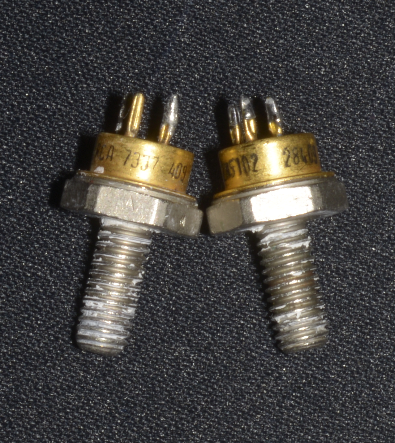
RCA 2N5102, coded and marked
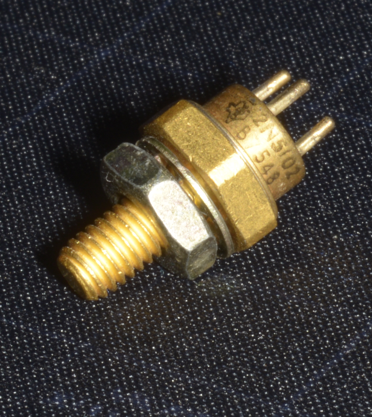
Texas 2N5102
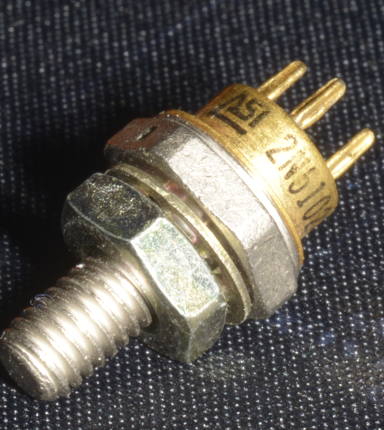
ASI 2N5102
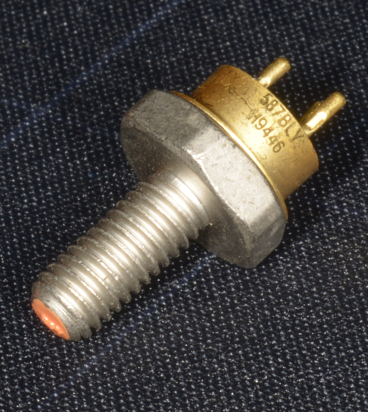
Philips 587BLY
In total, ten R.F. transistors are used to take the nominal 2W drive from the Low-Level board up to 125W. Initially these were type 2N5102, by RCA and maybe later by Texas and/or ASI. Interestingly, the 2N5102 is described as a VHF device, intended for Class-C AM avionic transmitters. It has a specified output of 15W with a maximum dissipation rating of 70W. hFE is given as between 10 and 100. Data on the 587BLY is scant, however it does appear to have been designed for use in military HF transmitters with roughly double the current and power rating of the 2N5102. The 2N5102s by RCA and ASI do not include a protection diode between Collector and Emitter, whereas the Texas-manufactured 2N5102 and Philips 587BLY do.
The input pair is a Grounded-Base Class-B (Push-Pull) stage. Since the current-gain of such a stage is always less than 1, the voltage gain is by definition, a function of the input and output resistances. I suspect this also implies that the hFE of these devices is not necessarily critical, although it is important that they are closely matched (see later for details of a substitution experiment).
The output from the input pair is then transformer-coupled to the output stage which actually takes a bit of getting your head around. The output stage consists of four pairs of transistors where, according to the manual, each pair is operated in push-pull. However, since the Bases of each pair are clearly in parallel, as are the Collectors, my opinion is that TR1 and TR2 are in parallel. The same applies to TR3 and TR4, TR7 and TR8 and finally TR9 and TR10. However, TR1/TR2 pair and TR3/TR4 pair are operated in Push-Pull, as are TR7/TR8 in conjunction with TR9/TR10. That is my interpretation ... as I said, it takes a bit of getting your head around.
The manual is most specific when talking about replacing these transistors ... stressing that transistor types must NOT be mixed. This is understandable, considering the balanced nature of the design and the fact that two types of transistor were available. Unlike the 2N5102, the 587BLY includes a built-in C-E protection diode.
I was fortunate to come upon matched sets of eight 587BLYs, although it isn't thought that these were specifically intended as replacements for the MM420. But I wouldn't rule it out. As part of my investigation I found that per type, as the date of manufacture advanced, the measured hFE increased ... early 2N5102s typically exhibit an hFE as low as 15, while later ones yield hFEs around 35 to 45. Similarly, some 2N5102s manufactured by ASI give much higher hFEs ... some yielding in excess of 150! Given that the voltage gain of the High-Level Board input-pair is governed by the input and output networks, I substituted a pair of 2N5102s with hFE of 35 with a pair with an hFE of 135, with no adverse effect. As far as the pair of output quads are concerned, I would caution against replacing individual transistors UNLESS you are prepared to measure the hFE of each of the eight and match any replacement devices accordingly ... which is likely why Racal made replacement 587BLYs available in packs of eight. As a footnote, it might be OK to replace the input pair with different matched devices if, and only if you remember to change the value of 5AR18 and 5AR36 accordingly (see table above)
The Low-Level Board ...
Original unmodified PS314 PCB
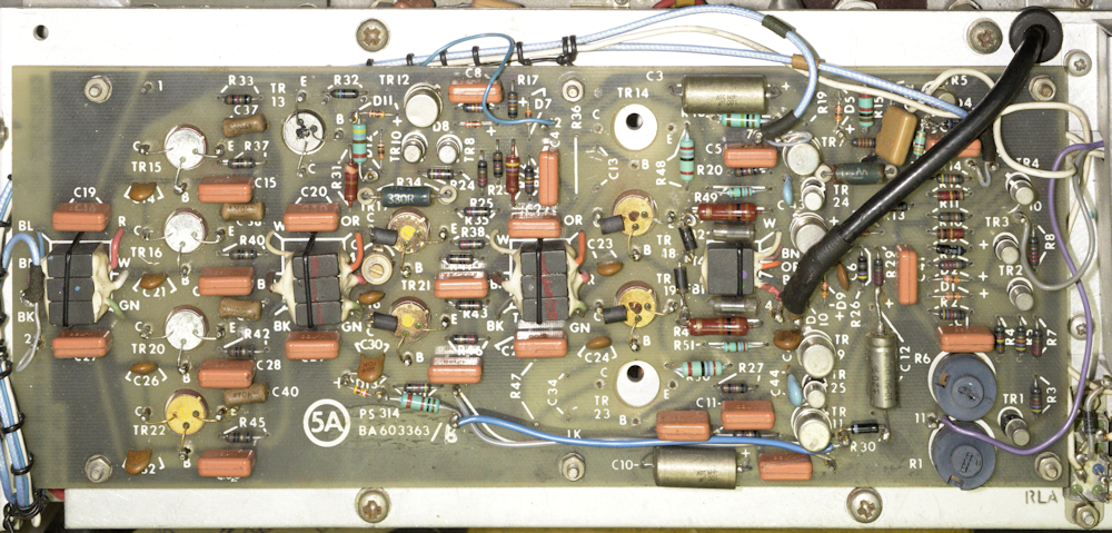
Modified PS314 PCB
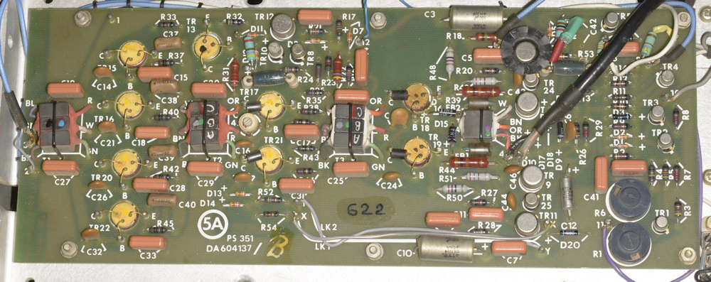
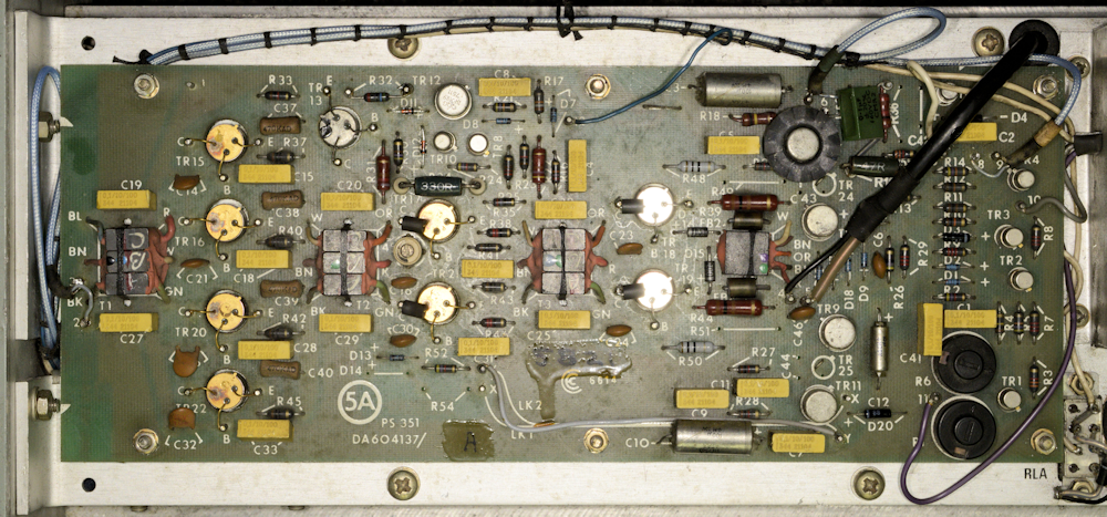
PS351 Low Level Board
PS351 Normal (short) ALC time constant
Racal described the two ALC time constants as Short-CR and Long CR. Note that Short-CR boards are missing TR24, TR25, R49, R51, D14, R54, C43 and C44. LK1 is also not fitted.
Other peculiarities ...
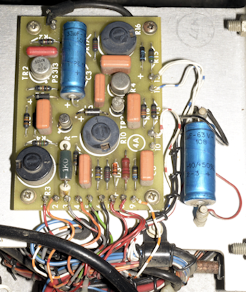
PS313 on early serial Stabiliser Module
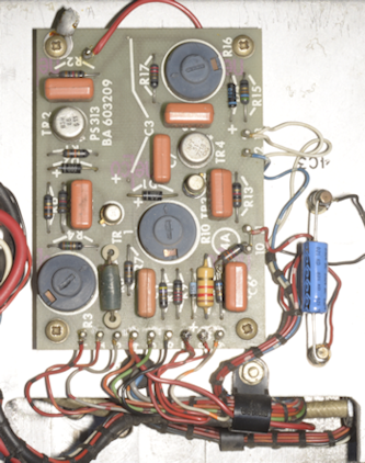
Another early PS313
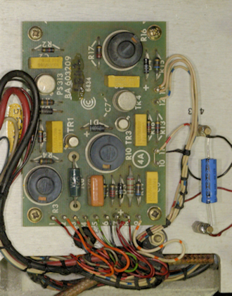
Later PS313
If you look at the above three photographs it is evident that something odd is going on. The two outer photographs might be considered later boards because they don't have the retro-fitted resistor on the right (centre photograph) as it now features on the PCB. C3 is fitted on the one on the left, omitted in the middle photograph and is missing from the silk-screen in the third photograph. C7 is also missing from the third photograph, as is R7. I think this is what might be termed incremental design? Ignore the wire going to the top left of two of the boards ... all will be revealed soon enough.
Just what is that multiturn pot doing?
Current Transformer mod
The image on the left should be viewed in conjunction with Fig. 21 in the TA.1813 manual, and shows how the transformer T3 integrates with the MM320 wiring. This mod is clearly intended to respond to high transient spikes in Collector Current and fire the thyristor, which would be seen as an over-current event, triggering the crowbar in the Stabiliser Module. What the diagram doesn't show is that in ALL installations of this mod, there is an 820R resistor across the transformer secondary.
Alternative Current Transformer mod
The image on the right shows how this mod is integrated into MM320s where the MM420 is configured for short time-constant ALC. Note the inclusion of the 820R resistor. Looks like wiring the rectified output of the transformer directly to the thyristor didn't work as expected. Maybe it was too sensitive ... hence the zener and decoupling capacitor.
Another Current Transformer mod
The image on the left shows the implementation of the mod found in seven of the eight MM420s that I have seen that are configured for long time-constant ALC. (The eighth MM420 was an early example that didn't have the mod fitted.) In this configuration the rectified output from the transformer is fed to the base of TR2 on the PS313 board in the Stabiliser Module. The sensitivity of the circuit can be set via the potentiometer. I have no details on how to set this up.
On one occasion, this particular modification had me going round in circles, trying to find why the crowbar on a particular PS313 board was asserting as soon as RF was applied to the input of the MM420. I found that removing the wire from the diode to the base of TR2 got rid of the problem, but that in no way resolves the issue. Monitoring the base of TR2 on an oscilloscope showed that there was a sizeable positive spike when RF (10mW) was applied to the amplifier. Why did this occur on this particular MM420 alone? I tried adjusting the potentiometer to no avail. In fact the level of the spike remained the same at all times. I eventually replace the multiturn pot ... and that resolved the issue. An interesting point to note here ... the potentiometer that I removed was different to the other six with this particular mod.
Here's another interesting curiosity ...
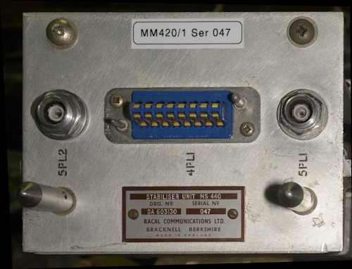
MS440 Serial Plate
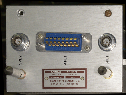
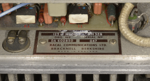
MM420/3 Serial Plate
Three of the eight long time-constant MM420s came with 'Dymo' printed labels on the front. It was only when I looked at the end-plates that I realised why, or at least I had good reason to think why. The image above-left is typical of one of the three, whereas the image above-right is typical of the other five, and the three configured for short time-constant ALC. The 'Dymo' label on the front reflected the serial number on the back. However, the serial plate identified the unit, not as an MM420 but as an MS440 ... which is actually what it is! The rear of all MM420s is actually the rear of the MS440 Stabiliser Unit. In fact, an MM420 comprises an MS440 Stabiliser bolted to an MM320 125W Module ... see the images below.
MM320 Serial Plate
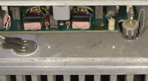
Missing MM320 Serial plate
Early in production, it probably made a lot of sense to have all MM420s fitted with modules with matching serial numbers. This might explain the 'Dymo' label stuck on the front. However, nowhere on these three MM420s could I find anything identifying them as MM420s, or which variant for that matter. In retrospect, it probably makes more sense for the MS440 to carry the serial plate of the MM420 to which it was to be part of. Worth mentioning ... When ever the serial label on the rear identifies the whole unit as an MM420, neither the MM320 or MS440 carry serial/identification plates.
A little detective work on my part identified these three amplifiers as MM420/1s
Conclusions and typical faults ...
To be honest, to me, the MM420 appears to be a robust and reliable RF amplifier. Apart from the 2N5102s and 587BLYs that I removed and/or replaced as part of my initial task, I only encountered one faulty transistor out of eleven PS315 High-Level boards. On the other hand, I had cause to replace multiple 2N3553s and 2N3866s on various Low-Level boards and a couple of transistors on the chassis of one MS440. In ALL cases the reason for replacing these transistors was mechanical failure where at least one terminal had snapped off. See the photographs below.
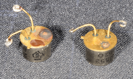
Damaged 2N3866 and 2N3553
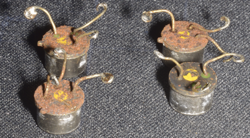
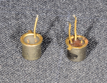
Badly corroded transistors
Two broken transistors from an MS440
Two damaged BC107s
Top-Left: Shows a 2N3866 and a 2N3553 removed from a Low-Level board with snapped-off Collector terminals. It is interesting to note that in each case there does appear to be discolouring of the plating where the terminal was attached.
Top-Right: Shows four transistors removed from Low-Level boards. Note the extreme nature of the corrosion. Although this appears to be quite common, it does not necessarily affect every device on the board.
Bottom-right: Shows two damaged BC107s. In each case at least one terminal has snapped off. The one on the left came from a Low-Level board and may have been due to physical contact. The one on the right came from a PS252 Protection board.
Bottom-Left: These two devices came from an MS440 Stabiliser Unit. During fault diagnosis I had need to lift the legs in order to isolate the devices. Note how the wires snapped some distance away from the hermetic seal.
I suspect that with TO39-can devices such as the 2N3866 and 2N3553 where they are mounted inverted with their legs wrapped around pins, stress is induced if the radius of the bend is too tight or if the bend starts at the hermetic seal. What I did with these and the two transistors from the MS440 was to use a 6mm drill-bit to limit the bend radius.
Finally ... there is the issue with the seemingly random resistor that is often found in series with the output of the 'Swingometer' network. It is clearly there as a protective device. I have heard it said that failure of 'swingometer' diodes, where they go short-circuit, is a known issue, and when that happens, TR5 on the Low-Level board is almost always blown. One solution appears to be to replace the 1N4149s in the 'swingometer' network with 1N4007s. Now to me that sounds like fitting a bigger fuse! Also, the 1N4149s are employed as detecors. I'm not convinced using a 1KV rectifier diode as a detector is going to be as effective. My first response would always be 'what exactly was the cause of the 1N4149s failing?' I would go as far as suggesting that such a failure is the direct result of very high VSWR. If this is the case, then the fault is not with the diodes themselves but with what caused the high VSWR and perhaps a fault elsewhere in the system, within the Transmitter cabinet, like the Cabinet VSWR Unit type MS447. Just a thought.
another load of faulty MM420s!
The other day, I came away from a friend's house with another five faulty MM420s. However, I will need to finish refurbishing his MA79G in order to complete his TA.127 before I start work on these.