How it might have been
22 minute read
March 2024
A bit of history first ...
In 1950 RAy Brown and George CALder Cunningham left their jobs at Plessey and invested the sum of £50 each in their own business, which within a year became Racal Engineering Ltd. By 1953, the British Admiralty was looking to upgrade the receivers on Royal Navy vessels and Racal had presented a proposal whereby they would supply several hundred Collins 51J-4 receivers that they would manufacture under licence in the UK. Racal's proposal was accepted. However there was a problem. Racal were seeking to source the bulk of the parts locally while Collins, quite naturally, were stipulating that all the parts be sourced from the USA. Secondly, when Collins carried out an inspection of Racal's manufacturing facility, they were not impressed ... which is likely an understatement. In hind sight, in the aftermath of World War Two, the physical condition of much of the London area still bore evidence of The Blitz. Collins thus refused the licence, leaving Racal with a contract to supply a product which it could not deliver. A tad embarrassing, one might say. We will come back to this.
Enter Trevor Lloyd Wadley, a South African genius ... the seventh child of a London-born immigrant. To cut a long story short, in 1941, while serving in the South African SSS (special Signals Services) in Alexandria, Egypt, in response to a request for a system whereby multiple transmitting stations could be simultaneously identified on a Cathode Ray Display, Wadley put together the hardware that would ultimately spawn the Racal RA17 receiver and RA66 Panadapter. This required a super-stable receiver, the heart of which was Wadley's beautifully elegant drift-cancelling system. This and a suitable amplifier and mixer was connected to the aerial input of a Hallicrafters receiver and was subsequently used to monitor increased Japanese radio traffic during the run-up to their attack on Pearl Harbour.
In 1953, Wadley presented an SAIEE paper on his designs, having already built a couple of identical prototypes for the South African Post Office as early as 1950. See below.
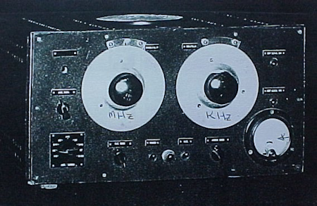
One of Wadley's two prototypes, circa 1950
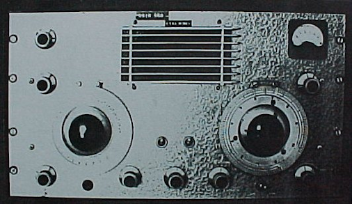
Prototype Wadley receiver manufactured by SMD, circa 1953
Wadley then, as part of a marketing trip, visited the UK where the BBC witnessed and were impressed by a demonstration of one of his receivers. At the time however, the styling attracted adverse criticism and subsequent deviations from Wadley's layout were to result in a significant increase in unwanted mixing products. To be honest, looking at the two photographs above, it isn't difficult to see why the physical look of the receiver was met with a negative reaction. My research into this event did not identify the receiver in question, Wadley's or SMD's. While Wadley's own prototype has a 1930's look, SMD's prototype, in terms of front panel layout, looks suspiciously similar to that of an RA17, and sorry, but that loudspeaker grill is hideous. Horace Dainty, MD of SMD, who made the prototypes, did allude to a cast aluminium chassis with compartments for the filters to be the ultimate solution. Then, the following year, 1954, while on an official trip to the UK, Frank Hewitt, a long time associate of Wadley, heard about Racal's predicament regarding their Admiralty contract for which they had no receiver. It was through Hewitt that Wadley was hastily deployed to Racal to assist in the design and build a new receiver from scratch. Fortunately, work on the die-cast chassis was well under way in South Africa.
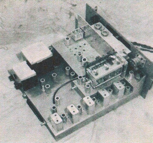
Prototype RA17 Receiver
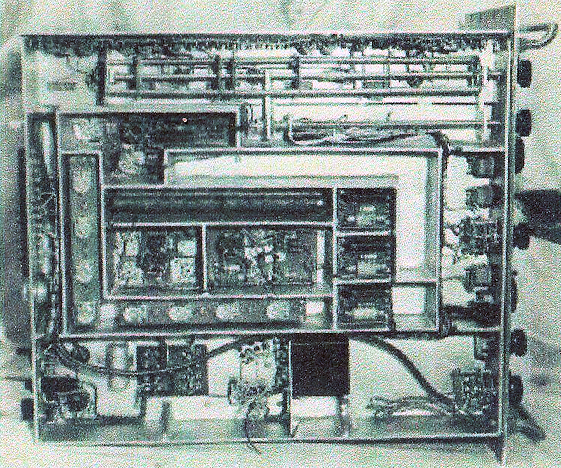
Prototype RA17 Receiver, underside, partially constructed
So there you have it ... history lesson over. But what of the Collins R-388 or 51J4? Racal had actually constructed an anonymised 51J-4, and it was this receiver which so impressed the Admiralty that the original contract was granted.
Towards the end of 2023, I was asked by an acquaintance if I might like to have a look at a Collins R-388/URR aka 51J-4. Apparently there was no audio output and it looked like someone had modified the circuitry around the detector. You know what that means ... Someone's attempt to force a receiver NOT designed to resolve SSB to do just that!
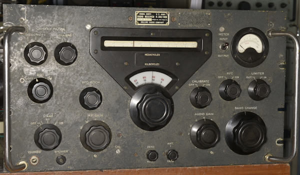
The Collins R-388/URR, as received.
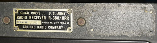
Left: The serial plate identifies this as R-388/URR Serial No. 600, manufactured as part of Order No. 3167-PHILA-51, which tells us that it was manufactured by Hallicrafters.
Right: Note the date-stamp to the right of the antenna connector. This 388 was manufactured in June of 1954. The mains cord and fuse holder were transposed. I rectified this and fitted a correct-size fuse holder. The smoothing pack is not the original octal-based type but the replacement has been sympathetically installed. The PTO is showing signs of serious corrosion, but apparently works well. Numerous screws and panels/covers are missing. The holders for the drum illumination bulbs are not original. I'm sure the screws either side of the serial plate are for the lamp-holders, yet the ones fitted are simply jammed between the front panel and the brackets supporting the drum. The panel meter is not correct and may actually be from a Racal RA17C-12. The yellow tint on the chassis appears to be painted on as I found that using IPA to clean part of the chassis actually dissolved the 'paint'.
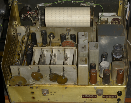
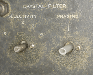
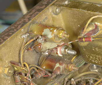
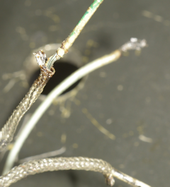
Left: I noticed that the Crystal Filter module was loose. This little module is very similar to the one in the Marconi CR100. In the R-388 the signal is fed through a 465KHz filter, then various capacitors are effectively switched across it to 'slug' the response and thus present different bandwidths ... crude but effective. This method of creating narrow bandwidths requires that you identify the actual frequency of the 465KHz crystal before aligning the IF stages, since they need to be tuned to the resonant frequency of the crystal filter. The reason why it was loose was due to the one and only screw being missing. Note the shocking condition of the coax braid in the centre. Whilst poking around in this area, I noticed that two out of the four nuts securing the mains transformer were missing and a third was loose. UNC hardware is not something that I have a huge stock of. Luckily I had just enough nuts etc. to screw everything down tightly.
Right: Here's something odd. When I saw this, I was initially sure that this isn't factory spec. The shaft of the phasing capacitor turns out to be a rather rough-cut length of plastic tube. My initial thought was that the original extension shaft might have been lost. But a look at the circuit diagram shows that neither the stator or the rotor of C188 are grounded, so it makes a lot of sense that the shaft should be non-metallic as it passes through the hole in the front panel. The fact that it is somewhat rough rough-cut might imply that the original was in fact lost.
Note also the discolouration of the front panel behind the knobs. Is it discolouration?, or is that the original finish? because this peculiarity is present behind ALL the knobs.
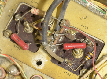
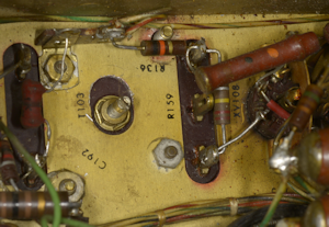
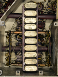
Left: I could have been forgiven for thinking that I had found all the missing or loose screws. Nope! As I pondered the rat's nest of mods around the detector and audio stages I noticed this ... a vertical row of enamelled wire-wound resistors where the middle one was floating ... supported only by the wires at either end. I can't remember which resistor this is, but it was otherwise in good condition, so, yet again I found some suitable hardware, this time metric M5 and resecured it. I wonder why the original screw had been removed.
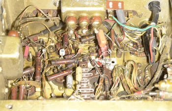
Left: This is what the area around the detector and audio stages looked like. Try figuring that rats-nest out! I didn't even attempt to try to trace it out. I decided to check all the valves on my VCM-163 and rejected four 6AK5s, one E180F and the 6AQ5. The latter exhibiting shocking heater-cathode leakage. Even after putting it back to 'factory standard', there was still absolutely nothing out of the loudspeaker.
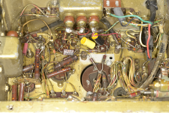
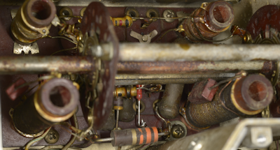
Right: Original circuity restored.
I should have guessed ... removing the front panel revealed more modifications.
Above, left to right ...
The yellow wire on the main ON/Off switch looks like a modification but it turns out to be correct; so why is it so long? And what are these blue coaxes for? The middle photograph shows some shocking wiring to the Audio Gain Control. The photograph on the right is the Limiter Switch which has been glued back together again and C209 looks like it has been replaced. I removed all the blue coax cables as I could not see what their purpose was and replaced C209. Still no output from the loudspeaker.
Left: Tracing the detected audio, I found that something on the Limiter Switch was shorting the signal to ground. The two coax cables are self explanatory but I never did figure out where the white wire soldered to the braid of one of the coaxes came from.
Right: The culprit turned out to be a rupture of the inner insulation on one of the coaxes, allowing the inner and outer to short. Fortunately the service-loop was long enough to allow the damaged section of coax to be removed.
Bingo! I now had audio from the loudspeaker. I was even picking up some local AM broadcast stations. Strangely though, despite it being switched off, I got the impression that the Calibrator was running. A prod with an oscilloscope probe proved this to be the case, although tweaking the front panel Calibrator adjustment had no effect. There was a reason for this. More on this shortly. Curiously, leaning on the top of the front panel 'stopped' the Calibrator running. So off with the front panel ... again. The cause of the Calibrator running even with the switch in the Off position turned out to be the switch itself. See the photograph above with the three switches. The one on the left controls the Calibrator. Like the Limiter Switch, it is a simple two-way affair ... so why is it a different type? Such is the difference that the Calibrator switch wafer is further away from the the front panel ... so far in fact that one of the solder-tags was making contact with the outside of the tuning gearbox. Bending the tags back towards the front panel resolved the issue.
Location of C224 with respect to the calibrator.
The Calibrator in the R-388 is very similar in design and implementation to that in the R-390 and R390A, in that harmonics from the 100KHz crystal are injected into the 1st RF stage. At first this can appear odd if you are familiar with the calibrator in the RA17 etc. which is injected at the 2nd IF. The reason why Collins inject into the 1st RF stage is actually quite obvious when you think about it. Due to the way coverage of 1MHz to 30MHz is implemented, the R-388 and R-390 etc. can be single or double conversion, thus it is easier to cover all options by injecting right at the front end.
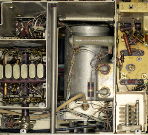
The reason for the Calibrator front-panel adjuster having no effect was glaringly obvious ... The variable capacitor, C224, was not actually wired. And another thing, it is mounted nowhere near the associated circuitry ... why? See the photograph above ... The Calibrator (V104 etc.) is located in the compartment top left. C224 is located in its own compartment bottom right. The circuit diagram indicates that the connection between C224 and V104 Anode is a coax cable. That implies at least 25cm of coax! Even the annotated photographs in the manual show a coax cable passing through the bulkhead into the area beneath the PTO, running the length of that compartment before looping under then into the compartment enclosing C224. I tried emulating this in the knowledge that such a length of coax was going to exhibit a significant capacitance that would likely 'swamp' C224. It had zero effect ... hmmm? So I took the coax out again.
The receiver was almost working, but I noticed that one of the IF transformers T103 was loose and causing fluctuating sensitivity. See the photograph on the right. Two of the UNC nuts were missing. I managed to replace one, but since the other stud was right under the 10K resistor (R136), I opted to leave it until later. Obviously someone had attempted to remove the transformer, although there was no evidence that they had succeeded. As it was, with three out of the four nuts now tight, the sensitivity was stable.
And then the drum cord snapped! Examining it revealed it to be NOT the nylon-coated wire that Collins used, but fine cord like that used in domestic radios of the same era. I didn't have any of the special Collins stuff, but I do have a supply on hand of rather nice modern kern-mantle nylon drive cord ... and I set about re-stringing it. And this is where I came upon some rather perplexing curiosities pertaining to the gearbox.
The first one being that the manual implies that replacing the drum cord is an easy matter since all one needs to do is rotate the gearbox such that it engages with the appropriate end-stop, corresponding to step 30. Except there was no such end-stop ... and with the drum-cord missing, I found that the gearbox was happy to rotate forever!! To identify step 30, I had to watch the wafer that selected the appropriate crystal then double check that the appropriate crystal was selected to identify position 30. With the drum duly re-strung, I wound the MHz knob clockwise (Yes, turning it clock-wise makes it count backwards) and verified that the appropriate crystal was selected for step 1 ... which it was. What I found worrying was that on its way from 30 back to 1, something very odd took place within the gearbox which would manifest with the mechanism suddenly feeling tight and the plate closest to the front panel appearing to bulge outwards. This could be averted by changing direction, then moving back again. Sometimes it would work, other times there would be a disconcertingly loud clunk. A look inside the gearbox revealed something very disturbing ... one of the large gears was actually wavy! See the photograph below.
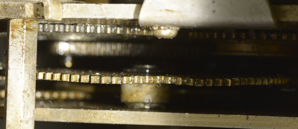
How on earth did this happen?!
I've worked on two R-390As and my own R-390 and have never seen the likes of this. This has to be the result of a something being used as a lever ... maybe to un-jam the mechanism? But to do that to a gear is nothing short of vandalism! Another thing that I noticed, which is quite common in these Collins gearboxes is the over-zealous application of grease that people cram in there. In truth, these gearboxes require only a small application of light machine oil. Too much grease encourages dirt to be collected and who knows what else? I suspect that if I were to remove the gearbox on this R-388 and pump solvent through it, I might actually find the missing end-stop! Maybe that is what is causing the obstruction.
The alignment procedure for the R-388 is similar to that in the R-390 and R-390A and I soon had it 'singing' but lacking in sensitivity. Into a good quality loudspeaker, the output from the 6AQ5 was very nice indeed. Not only was it a bit deaf, but it was not working on step 3. One out of thirty can't be bad, I thought. The funny thing was though, the local oscillator was working on step 3, so why the lack of signal? ... where was the break in signal continuity? And then the drum cord snapped again!
Having quickly replaced the drum cord a second time, and verified that there was nothing jamming the gearbox, I 'chased' the signal from the antenna socket towards the RF amplifier and confirmed that the signal wasn't getting through on step 3. I was able to confirm that the appropriate transformers were intact, so the issue had to be switch-related ... and that's where it gets really mind-bending. This is where the simplicity of Racal and Wadley's drift-cancelling MHz selection system contrasts so dramatically with Collins' unbelievably complex system employing ten quartz crystals and eight switch wafers.
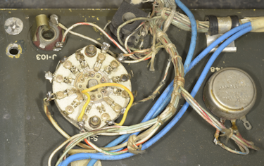
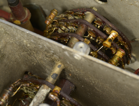
Left: The ten HC6U crystals and two of the three wafers associated with their selection. 1st, 2nd or 3rd harmonics are selected where appropriate. These are 17-way wafers and the gearbox ensures that the wipers only move every second step.
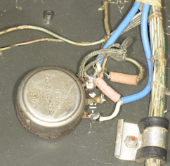
Right: Here is a close-up of the two wafers that form the I-F Switch which swaps the 'sidebands' between Odd and Even steps. This photograph was primarily taken to highlight the frustrating inaccessibility of many of the components in the R-388. Here I had to be creative when replacing R124 (2K2) in the centre.
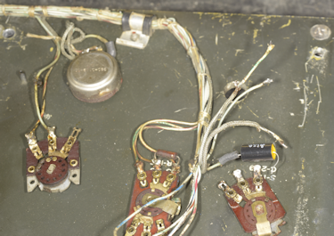
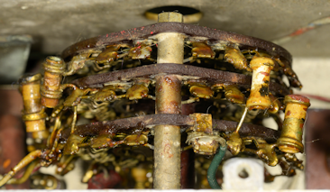
Left: This photograph shows the four wafers associated with band/step selection and illustrates the inaccessibility of the three wafers at the rear, mounted between two screens
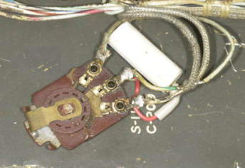
Right: This is a close-up of the three rear wafers. Note how close they are to each other. That's not flux on the tags, that the horrible yellow 'paint' that the chassis is covered in. In fact almost all solder joints throughout this particular R-388 are covered in this stuff.
Like the crystal-selection wafers, the step-selection wafers are also 17-way. But what makes this such a complex system to get your head around is the fact that these four wafers are of the make-before-break variety ... and not only that, the wiper moves half a position per step. Thus, on step 1, the wiper points at tag 1. On step 2, tags 1 and 2 are both connected to the wiper. On step 3, the wiper points at tag 3 ... and so on a and so forth ... implying that in some cases two tuned transformers are in parallel.
So, having re-strung the drum cord a second time and ascertained that there was a switch contact issue somewhere in that three-wafer sandwich at the rear, I gave it a generous blast of IPA and closed up the workshop for the night. Imagine then my disbelief when I switched it back on the following morning and found that this R-388 was no longer not working on just one band ... it was instead now only working on bands 1 and 3 ... WHAT!
I have a theory of what might be going on here, and it concerns that yellow paint-like covering that has been daubed literally everywhere. What is it?
Being ex-Racal, I am very familiar with the corrosion inhibiting practice of 'alocroming', where aluminium parts were treated in a dipping process resulting in an excellent corrosion resistant chromate coating which is both flexible and dent-resistant. The finish being an iridescent gold colour. I have searched the internet for photographs of R-388s and have identified three different 'looks' or appearances. There are receivers where the chassis (predominantly aluminium) appears pristine and natural in colour. Others do look like they have been 'alocromed', where the aluminium parts of the chassis have a distinctive uniform yellow tint. Then there are others like this one, where the yellow colour looks like it has been painted on. I am now wondering if this 'paint' is a form of tropicalization ... added protection for humid or highly corrosive environments. Hence why even the solder joints have been 'painted'. And in the case of the three wafers that were generously sprayed with IPA; has this coating perhaps dissolved and 'run' into places where after the IPA has evaporated, it has formed a non-conductive barrier, resulting in multiple breaks in signal continuity?
Conclusions ...
At the time, the Collins R-388 was the first HF Communications receiver to offer the stability required to reliably resolve and decode RTTY, the chosen mode of the day for military comms. Hence the reason Her Majesty's Admiralty were keen to upgrade the Royal Navy's ageing CR100s. As I said at the start, this particular R-388 was missing more than a few screws and covers. As well as the mains transformer not being screwed down due to missing or loose nuts, only half the screws securing the two smoothing chokes were present. Add to that list, the missing nuts on T103 and the missing screw on the crystal filter.
I had been looking forward to working on this particular radio, as an example of what the fledgling Racal had hoped to manufacture under licence. As it turned out, this poor R-388 has clearly been through 'the wars'. At the moment I have put it aside as I have a steady stream of RA17s etc. coming in for repair and realignment. As long as it is still in my possession though, I may return to it from time to time and try to clear the excess grease from the gearbox and maybe even attempt to flush out (literally) whatever is stopping the RF signal getting to the front end.
If Collins had granted Racal the licence to manufacture the R-388, would they have become the successful conglomerate that they ended up being? Given the flexibility of the RA17 and it's myriad of ancillaries, I think not. We have to thank Frank Hewitt for introducing Trevor Wadley to Racal for what then transpired. As they say, the rest is history.