Chasing an itch
5 minute read
... still in May 2007
Have you ever had an itch that whenever you scratched it, would move somewhere else? This is what I would liken the problem to that developed in my 9cm transverter. Exactly when the problem manifested itself and what caused it is unclear. Several months ago I noticed that the LO in my 9cm transverter would perform instantaneous frequency shifts, up and down for several minutes after switch on. Initially I put this down to the fact that the transverter was mast-mounted and what I was seeing was perhaps the effect of temperature differential. However as mentioned in an earlier page, the transverter was eventually moved indoors and re-built. The frequency hopping did not, as expected go away. As before, it would hop about for about five minutes after switch-on, then appear to settle down. However after about twenty minutes into a QSO, it would start again, with shifts at 3.4GHz being as much as 7KHz ... Not the easiest signal to follow!
The initial suspect was the 10nF chip capacitor decoupling the supply to the JFET. This was replaced but did not rectify the situation. Several months passed and other projects took precedence until I revisited the issue once more this week. Now having a GPS locked 10MHz source, against which measurements could be made, I was determined to get my 9cm transverter ‘on frequency’. Prodding the board gave the distinct impression that there was a dry joint or cracked smd component somewhere. Joints were wicked and re-flowed and the 10nF capacitor was changed again! But I still had a 'frequency-agile' transverter. My main problem was that once warmed up, the problem was extremely difficult to duplicate. But, I had noticed that lateral pressure applied to the top of the 407MHz helical filter did re-create the sort of frequency shift that was symptomatic of the problem. My mistake however, was to assume that this was flexing the board sufficient to disturb a cracked joint or component. I re-flowed specific joints again, but to no effect. Then I found the culprit. I removed the metal ‘slugs’ from the filter and blew compressed air into it in case there was some debris inside . . . which there wasn’t. Then I noticed that one of the ‘slugs’ was discoloured and looked like the thread had maybe a resin deposit on it. I cleaned it with a glass-fibre brush and refitted both ‘slugs’. On re-tuning the filter, I noticed that the ‘slug’ which I had cleaned tuned smoothly, whereas the other, which appeared clean, exhibited erratic behaviour . . . the voltage measured at the test point was erratic. I removed this ‘slug’ and gave it the same treatment. On replacing it, the erratic nature was gone. I placed the transverter in the refrigerator for a few minutes to simulate a cool night then allowed it to return to room temperature before switching it on. This time the LO did NOT hop around. The itch was finally gone!
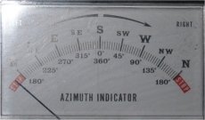
Another problem that I had on 9cm was related to my ancient AR-40 rotator, which after 30 years of service was now exhibiting around 10 degrees of lateral slop. I’m not sure what the beam-width of my home-made 9cm 48 element quad-loop yagi is, but a gust of wind was sufficient to move the stub-mast atop the AR-40 to such a degree that signals could vary by as much as 20dB! I was however fortunate enough to be given a Yaesu G-400 rotator. The G-400 like most medium/heavy rotators has an ingenious friction brake which works on the reverse ratio of the gear-chain and therefore, once stopped, it is more or less rigid. The G-400 controller uses a moving coil meter to indicate the position of the rotator and a curious feature of this display is that it appears to be manufactured for another planet!. (See the image below). Note that North is given as 180 degrees and South as 0/360 degrees . . . Eh! Why?

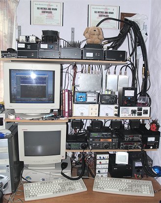
The photograph on the right shows the revised operating position as of May 2007. I have recently acquired an Icom 706MK2G which now replaces the IC706MK2, IC260E and Microwave Modules 70cm transverter. Note that the GPS Disciplined OCXO now sits on the top shelf where the 70cm transverter once sat. It is a sad fact that my trusty IC260E probably has zero market value. It has given sterling service since 1979, so I have decided to keep it in service for sentimental reasons and is now permanently connected to an external vertical dipole, like the TR8400.
