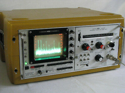
Systron Donner Spectrum Analyzer Type 809-1 - Solving the Frequency Calibration Issue
11 minute read
This post is part of the series 'Systron-Donner Type 809-1':
Not only that, but I didn't like the feel of the vernier control so I had a look inside, behind the front panel. I am no stranger to tuning-scale drive cords, having re-strung a few vintage radios over the years and had to figure out how to string the cursor in my RA137A. The drive-cord arrangement in the Systron Donner is fiendishly clever when you finally figure it out. I can find no description of it in the manual either. It was immediately obvious that the frequency calibration issue was mechanical, NOT electronic. Unlike old domestic radios where the drive-cord is usually wound off and on a large drum-like disc, the Systron Donner simply uses the tuning control shaft. As the cord is wound off one end, the other end of the cord is wound back on the other end of the shaft. However in my case it looked like the shaft wasn't long enough and as the shaft was turned clockwise the turns of cord being taken up on the shaft, pulling the cursor to the right, began a second layer about mid-scale.
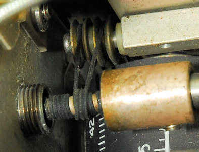
Left: The culprit! The tuning control shaft runs through a bush in the front panel before connecting to a 10-turn pot via a hefty shaft coupler. Note how the cord has started to form a second layer. The effect of this probably increases the potential circumference of the shaft by as much as 6mm!! This results in the cursor being pulled further along the scale per turn. This explains the sudden mid-scale loss of accuracy ... when the cord formed the second layer.
Watching the cord as I turned the shaft, I noticed that the extended thread on the panel bush was playing a part in this. When the cord was closest to the front panel it actually brushed against the end of the bush causing it to change direction. Thus, not all the shaft was being used.
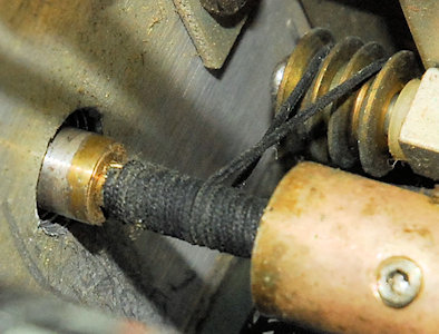
Right: With the bush removed, and a little help from a long screwdriver, the cord now tracks beautifully back and forward along the length of the available shaft. I also found that the shaft-coupler had not been pushed fully onto the shaft of the 10-turn pot. Rectifying this situation effectively moved the cord further away from the front panel and bush.
It is interesting to note that the entire length of available shaft is used. The tuning is carried out by a 10-turn potentiometer. So lets do some maths: ... The approximate maximum cursor travel is 120mm, so each turn moves it 12mm. Divide that by pi (3.14) and we get a shaft diameter of 3.8mm, which looks about right. If you count the turns of cord in the photograph you will see that there are about 13. Not all the cord is wound out.
Left: It struck me that if the tuning unit had originally been fitted with a vernier control, then the bush might not have protruded so far into the inside of the unit. If this were the case and the vernier was replaced with a plain knob at some time, then this may well have been what caused the calibration issue in the first place. I suspect that the 'plain' knob on my 809-1 is actually part of the original vernier control.
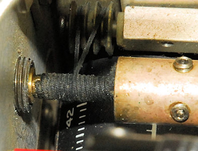
I found a 2mm-thick round plastic spacer to prevent too much of the bush thread protruding into the inside of the Tuning Unit and fouling on the dive-cord. As can be seen from the photograph, this has worked beautifully.
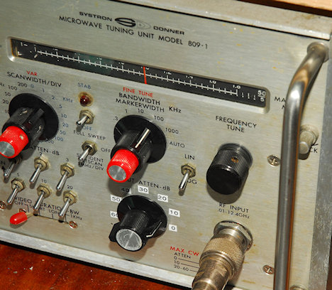
Right: Three things to note: The little stick-on annotations reversing the attenuator switch, mentioned in the previous article. The addition of the 2mm spacer between the bush and the front panel, behind the Frequency Tune knob ... and the fact that the cursor is aligned on 1GHz.
Left: The end result! Using my newly constructed extender cable, I was able to operate the 809-1 Tuning Unit out of the main chassis. This gave me access to the Upper and Lower frequency adjustment pots ... a bit akin to setting the LF and HF points in a communications receiver. I knocked up a harmonic generator using a couple of Schottky diodes back-to-back and fed it with +10dBm of 600MHz from my Adret 740A. This produced a nice peak at 1.8GHz and I used this to set the HF end of the tuning scale and the 'zero marker' to set the LF end of the scale (on Range 1).
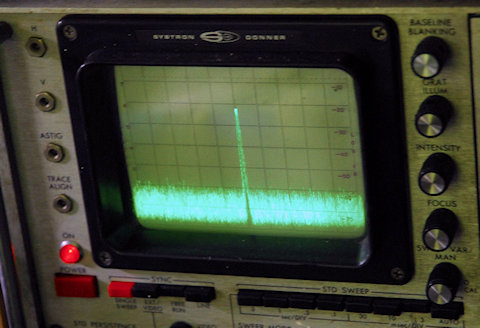
The photograph above shows the 1GHz signal with the Cursor on 1GHz and the Span/Div set to 1MHz. I was delighted to see the signal jump exactly 1 division for every MHz plus or minus of 1GHz. The accuracy is spot on all the way from 1.8GHz down to 10MHz. Job done!
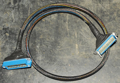
Right: The Tuning Unit extender cable made using the two Cinch connectors generously supplied by Allen, N7CGH
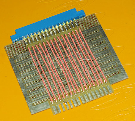
Left: Here we have a card extender (board supplied by David, WB0GAZ). I've actually had the parts to make this board since 2016, but put off making it until this week. Note the multiple key-slots at the bottom. These are necessary since most of the boards in the Tuning Unit are uniquely keyed. I haven't had the need to use this board yet ... fortunately.
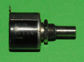
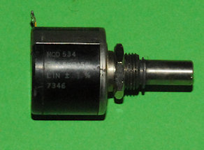
I could have left it there, but something was niggling me. Occasionally, the spectrum displayed on the screen would quickly drift to the left ... easily corrected by pressing on the Tuning knob! I knew exactly what the problem was. There was about 1mm of longitudinal slop on the 10-turn tuning pot, as can be seen in these two photographs.
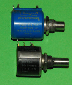
Left: The smaller Spectrol potentiometer is +/- 5% tolerance with +/- 1% linearity. The larger Bourns potentiometer is +/- 3% tolerance and +/- 0.2% linearity.
Before removing the old one, I first set the cursor to 0.8GHz and carefully pulled the shaft-coupler away from the potentiometer. I then carefully removed the pot from its bracket and disconnected the wiper so that I could measure the resistance to one end. That way I could pre-set the new pot to the same value.
Once the new pot was mounted and the shaft-coupler re-engaged I found that the pot mounting-bracket was attached to the side of the unit by a single screw. Obviously there is some other point of attachment but it wasn't visible. Loosening this screw allowed me to align the tuning shaft in the centre of the hole in the front panel and eliminate the lateral pressure on the pot-shaft.
Obviously the unit needed the upper and lower frequency limits reset. Pre-setting the new pot to the same point as the old one however meant that only the smallest adjustment was necessary. I did temporarily fit one of my vernier knobs but being smaller than the original, it looked odd and to be honest I don't see the point in it since there is no correlation between the vernier read-out and the Tuning scale. So I re-fitted the plain knob ... looks much better. The tuning is now smooth over the entire length of the scale and accuracy is spot-on.
- Systron Donner Spectrum Analyzer Type 809-1
- Systron Donner Spectrum Analyzer Type 809-1 re-fit
- Systron Donner Spectrum Analyzer Type 809-1 - Solving the Frequency Calibration Issue
June 2020
Having replaced the faulty input attenuator, my 809-1 was more sensitive than ever, but something was just not right with the frequency calibration. This was not a new problem either. I remember back in the 1980s when it was assigned to an MoD contract at the Racal site where I worked ... the frequency calibration was more 'ball park' than accurate.
So I figured that it was time to get to the bottom of the problem, and with my newly assembled extender cable, I would now be able to carry out the necessary adjustments on the 809-1 Tuning Unit out of the main chassis.
The problem with the Frequency calibration was this ... Initially, if set such that the cursor was close to the left edge of the scale, the accuracy was actually quite good. However as you tuned up in frequency there was a noticeable 'jump' about mid-scale where the actual frequency was significantly lower than indicated ... and it got worse as the frequency increased.
Last night I discovered the culprit ... quite by chance. I had been studying the calibration procedure in the service manual. Naturally, there is no point in proceding with an electronic calibration until the mechanical 'alignment' is confirmed. To this end, the manual described the method for setting the left and right cursor positions. This included a line which said to turn the tuning knob nine and three quarter turns clockwise.
This sounded a little bit too precise, given that the tuning knob on my 809-1 is a simple black knob about half an inch in diameter. Could it be that it should be a vernier control? Sure enough, I found a photograph, albiet of an 809-2A, with a vernier control. I have a bunch of slightly smaller vernier controls, so I set about replacing the plain knob with what I figured was more authentic. What I discovered was quite revealing. With the vernier control attached, I could only get eight and a half turns before the cursor ran up against the end of its travel.
An 809-2A Tuning Unit with a vernier control
Not only that, but I didn't like the feel of the vernier control so I had a look inside, behind the front panel. I am no stranger to tuning-scale drive cords, having re-strung a few vintage radios over the years and had to figure out how to string the cursor in my RA137A. The drive-cord arrangement in the Systron Donner is fiendishly clever when you finally figure it out. I can find no description of it in the manual either. It was immediately obvious that the frequency calibration issue was mechanical, NOT electronic. Unlike old domestic radios where the drive-cord is usually wound off and on a large drum-like disc, the Systron Donner simply uses the tuning control shaft. As the cord is wound off one end, the other end of the cord is wound back on the other end of the shaft. However in my case it looked like the shaft wasn't long enough and as the shaft was turned clockwise the turns of cord being taken up on the shaft, pulling the cursor to the right, began a second layer about mid-scale.
Left: The culprit! The tuning control shaft runs through a bush in the front panel before connecting to a 10-turn pot via a hefty shaft coupler. Note how the cord has started to form a second layer. The effect of this probably increases the potential circumference of the shaft by as much as 6mm!! This results in the cursor being pulled further along the scale per turn. This explains the sudden mid-scale loss of accuracy ... when the cord formed the second layer.
Watching the cord as I turned the shaft, I noticed that the extended thread on the panel bush was playing a part in this. When the cord was closest to the front panel it actually brushed against the end of the bush causing it to change direction. Thus, not all the shaft was being used.
Right: With the bush removed, and a little help from a long screwdriver, the cord now tracks beautifully back and forward along the length of the available shaft. I also found that the shaft-coupler had not been pushed fully onto the shaft of the 10-turn pot. Rectifying this situation effectively moved the cord further away from the front panel and bush.
It is interesting to note that the entire length of available shaft is used. The tuning is carried out by a 10-turn potentiometer. So lets do some maths: ... The approximate maximum cursor travel is 120mm, so each turn moves it 12mm. Divide that by pi (3.14) and we get a shaft diameter of 3.8mm, which looks about right. If you count the turns of cord in the photograph you will see that there are about 13. Not all the cord is wound out.
Left: It struck me that if the tuning unit had originally been fitted with a vernier control, then the bush might not have protruded so far into the inside of the unit. If this were the case and the vernier was replaced with a plain knob at some time, then this may well have been what caused the calibration issue in the first place. I suspect that the 'plain' knob on my 809-1 is actually part of the original vernier control.
I found a 2mm-thick round plastic spacer to prevent too much of the bush thread protruding into the inside of the Tuning Unit and fouling on the dive-cord. As can be seen from the photograph, this has worked beautifully.
Right: Three things to note: The little stick-on annotations reversing the attenuator switch, mentioned in the previous article. The addition of the 2mm spacer between the bush and the front panel, behind the Frequency Tune knob ... and the fact that the cursor is aligned on 1GHz.
Left: The end result! Using my newly constructed extender cable, I was able to operate the 809-1 Tuning Unit out of the main chassis. This gave me access to the Upper and Lower frequency adjustment pots ... a bit akin to setting the LF and HF points in a communications receiver. I knocked up a harmonic generator using a couple of Schottky diodes back-to-back and fed it with +10dBm of 600MHz from my Adret 740A. This produced a nice peak at 1.8GHz and I used this to set the HF end of the tuning scale and the 'zero marker' to set the LF end of the scale (on Range 1).
The photograph above shows the 1GHz signal with the Cursor on 1GHz and the Span/Div set to 1MHz. I was delighted to see the signal jump exactly 1 division for every MHz plus or minus of 1GHz. The accuracy is spot on all the way from 1.8GHz down to 10MHz. Job done!
Right: The Tuning Unit extender cable made using the two Cinch connectors generously supplied by Allen, N7CGH
Left: Here we have a card extender (board supplied by David, WB0GAZ). I've actually had the parts to make this board since 2016, but put off making it until this week. Note the multiple key-slots at the bottom. These are necessary since most of the boards in the Tuning Unit are uniquely keyed. I haven't had the need to use this board yet ... fortunately.
Shaft in
I could have left it there, but something was niggling me. Occasionally, the spectrum displayed on the screen would quickly drift to the left ... easily corrected by pressing on the Tuning knob! I knew exactly what the problem was. There was about 1mm of longitudinal slop on the 10-turn tuning pot, as can be seen in these two photographs.
Shaft out
This is technically a precision component, manufactured by Spectrol, and I don't believe it to be a quality problem. This failure was unlikely to be Spectrol's fault. For a while I had been aware that the tuning action was not consistent across the scale. Basically the control was stiff at times. While I was correcting the issue with the drive cord I noticed that there was a distinct 'wobble' on the Tuning shaft which was more noticeable when the bush was removed. Essentially the mounting bracket for the 10-turn pot was not parallel to the front panel and running the shaft through a 10mm long bush (in the front panel) was putting lateral pressure on the pot shaft ... and over time it basically wore it out.
I really needed to replace the control ... how difficult could that be? Looking into the Tuning Unit, it wasn't obvious what the value of the potentiometer was, and the service manual was annoyingly unhelpful too! The potentiometer features on not one, but two schematics. In Fig. 9-7 R201 is given as 10K, and in Fig. 9-14 it is given as 5K. So I looked at the Parts List, only to find that it is simply listed as a Potentiometer.
Whether it was 5K or 10K was not an issue with me since I had at least one of each at hand. But I was hoping that it was a 5K pot as I had a couple of very expensive Bourns specimens just waiting to be used. Getting the faulty one out was not difficult, but it was a tad tricky, and I can confirm that it is in fact a 5K pot.
Bourns Vs Spectrol
Left: The smaller Spectrol potentiometer is +/- 5% tolerance with +/- 1% linearity. The larger Bourns potentiometer is +/- 3% tolerance and +/- 0.2% linearity.
Before removing the old one, I first set the cursor to 0.8GHz and carefully pulled the shaft-coupler away from the potentiometer. I then carefully removed the pot from its bracket and disconnected the wiper so that I could measure the resistance to one end. That way I could pre-set the new pot to the same value.
Once the new pot was mounted and the shaft-coupler re-engaged I found that the pot mounting-bracket was attached to the side of the unit by a single screw. Obviously there is some other point of attachment but it wasn't visible. Loosening this screw allowed me to align the tuning shaft in the centre of the hole in the front panel and eliminate the lateral pressure on the pot-shaft.
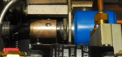
Bourns potentiometer fitted
Obviously the unit needed the upper and lower frequency limits reset. Pre-setting the new pot to the same point as the old one however meant that only the smallest adjustment was necessary. I did temporarily fit one of my vernier knobs but being smaller than the original, it looked odd and to be honest I don't see the point in it since there is no correlation between the vernier read-out and the Tuning scale. So I re-fitted the plain knob ... looks much better. The tuning is now smooth over the entire length of the scale and accuracy is spot-on.