A Linear LED Driver PSU
1 minute read
January 2018

Looking for the simplest design with safety built-in I found the TL783 voltage regulator. This is essentially a 700mA device so one of these could easily drive a single panel. However this requires a heat-sink … and even then, the heat generated is significant.
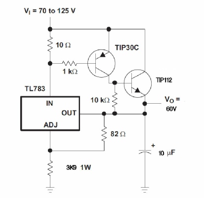
The image on the left is based on one of the application schematics taken from the manufacturer’s (Texas) data-sheet. The values 3K9 and 82R conveniently produce an output of nominally 60V off-load, dropping to 58V when delivering 550mA. This is sufficient to drive the panel to full brightness. The TIP112 is a power Darlington capable of sinking 2A, so there is now plenty of ‘headroom’.
This regulator is fed from a conventional transformer / bridge circuit with smoothing pack.

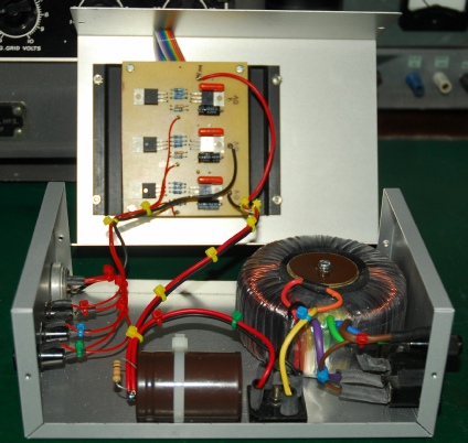
Left: An internal view of the completed light-panel power-supply. I chose to provide an independent regulator per panel and each output is independently fused. The TIP112s and mounted on the heat-sink. Although TO220 devices, the TL783s and TIP30Cs do not get more than slightly warm, so no need to heat-sink them.

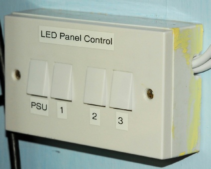
Left: This is the bank of switches which originally switched the individual SMPS units. I rewired it such that one switch applies mains to the PSU whilst the remaining three switches apply the 60V DC to the individual panels.